Every serious project has a phase that nobody talks or writes about much. It comes before you have a design, before you have an architecture, before you are even sure any of it is possible. You pick a direction and walk until you hit a wall, then you turn and try another way. You build things just to understand them, then throw them away. Sometimes a tool you wrote in an afternoon ends up lasting for years. Sometimes a week of work goes straight into the trash. Sometimes you get happy with what you learned and never bother to complete your project. This is pathfinding, and it is not optional.
The alternative is to design the whole thing and then discover you were wrong about something fundamental when you are halfway through the hardware.
This post documents that phase of the calculator project. Although I wrote and discarded many more, three separate programs remained checked in; one for each open question. The post ends with and an unexpected detour involving an infrared LED and a vintage HP printer.
A word about tools. It is common to treat pathfinding code as throwaway: messy, undocumented, just good enough to answer the question. That is a mistake. Fred Brooks named this pattern in The Mythical Man-Month: “plan to throw one away; you will, anyhow.” His point was that prototypes are inevitable, and the only question is whether you plan for it or get surprised. I planned for it, and I wrote everything carefully.
Proof: Can I Actually Do This?
I knew I could implement the four basic operations (+,-,*,/), that part was not in question. But the logarithmic and transcendental functions are a different matter. The usual approach in software is to call a library, but part of my curiosity was how various libraries compute higher-order operations, and then how calculators do that, and how they did that back in the 70s? In order to fully understand the algorithms, I had to implement them.
The Proof project coded that research. It is a deliberate strawman: quick, exploratory C++ code that tests specific algorithms for each higher-order function. Not a production quality, not a final implementation, just enough to verify that an approach works.
The functions it covers:
- Square root: several candidate approaches, comparing convergence and error. The natural candidate is the Newton-Raphson iteration:
x_{n+1} = (x_n + N/x_n)/2. This is one of the oldest known numerical methods. A Babylonian clay tablet designated YBC 7289, dated to roughly 1800 BCE and now in Yale University’s collection, shows √2 computed to six correct decimal places, likely using this iterative approach. - Logarithm and anti-logarithm:
ln(x)andexp(x), implemented using only basic arithmetic operations - Trigonometric functions:
tan(x)andatan(x), as the basic ones we need
It turns out these three categories are not as separate as they look. During this exploration I discovered that all these functions share a deeper algorithmic connection – a single iterative method that covers trig, exponential, and logarithmic functions alike – called CORDIC. Understanding this connection early on shaped which algorithm family I ended up using. Post 3 covers this in detail.
At this stage I was not concerned with exact BCD representation or final precision. The focus was entirely on the algorithms themselves: their convergence behavior and their computational cost. If one approach to computing ln(x) required 16 polynomial iterations to reach a usable result with 16 digits of precision while another converged in 8, that mattered, and this was where you find it out. I measured convergence empirically, watching how many iterations each algorithm needed and how the error shrank with each step. A reasonable convergence rate, even in floating-point arithmetic, gives confidence that a BCD implementation can be iterated to sufficient precision. The second criteria were the algorithmic complexity of each function: I needed to rely only on few basic operations and not kick the can down the road and use ever more complex terms.
More complex calculator functions can be derived from a few basic ones. Once I had these working, even crudely, the feasibility question was answered.
Mockup: What Should the Key Layout Look Like?
With the computational feasibility established, the next question was the key layout.
This sounds like a simple decision, but it is not. Designing a good calculator keypad is mostly about avoiding the many ways to get it just slightly wrong. The problems are often subtle: things that do not feel right, they require longer hand travel or an extra key press. Should ENTER be on the right edge or somewhere more central? Should RCL be a primary function or shifted? Where is the decimal point key in relation to the digit keys? HP, TI, and Casio have each developed their own conventions, and many people prefer a certain calculator vendor because they are already familiar with the layout.
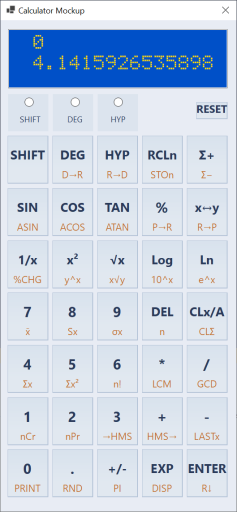
To help me with that, I wrote Mockup app which is a C# Windows application that lets me experiment with different layouts before committing to one. Layouts are defined in text files (layout1.txt, layout2.txt, etc.) that the application loads via a folder-browser dialog. To feel more real, the application implements most calculator functions, uses the actual HD44780 LCD font (the same font the hardware display will use) for rendering, so the screen looks pixel-for-pixel authentic.
I went through several layout iterations while I researched key positions of common commercial calculators. The biggest lesson (and not surprising) was that key placement of shifted functions matters more than you expect: a function you use frequently but placed behind a shift key becomes annoying within the first hour. The layout that survived had ENTER on the right-bottom edge, the basic operations grouped together, and the most-used scientific functions (sin, cos, tan, log, exp) as primary keys. Nothing extraordinary or novel. Maybe that was the point.
Code-wise, the layout description files that Mockup uses are the same files compiled into the calculator microcode. That simplifies the design flow and removes a possible source of errors. In general, I tend to have only one source of truth, which is then copied over, processed and reused across various modules, as needed.
Input: Number Entry Is Harder Than It Looks
The third open question was the number entry. This sounds trivial: the user types digits, you store them internally in a buffer. But on a scientific calculator with BCD mantissas, exponents, change of signs, deletes and possible overflows on input, the state machine has more subtle edge cases than you might expect.
Consider: what happens while the user is typing 0.005e10? The mantissa is being built in one buffer, the exponent in another, and the effective internal exponent (the one that goes into the register) is not what the user typed. It is the perceived exponent (what the user sees: +10) combined with a virtual exponent derived from where the decimal point landed in the mantissa (-3, because 0.005 = 5 × 10⁻³). The effective exponent stored is +7.
The mantissa is stored normalized: except for true zero, the very first digit has to be non-zero, even if the user types leading zeroes.
What happens if the user presses “e” without typing any mantissa digits first? (Answer: force the mantissa to 1, so e5 gives 1E+05.) What if the mantissa is so long it would overwrite the exponent display area? (Answer: ignore the e keypress until the user deletes some digits.) What does backspace do in exponent mode vs. mantissa mode? Once you start thinking about it, you find all kinds of crazy edge cases. I tested various calculators I had, and in the end, I mostly adopted the HP-like behavior.
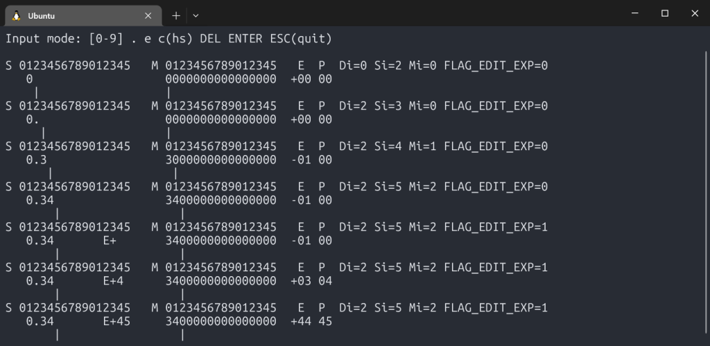
The Input project is a C++ simulator that implements the input heuristic, and it is interactive. You type keystrokes at a terminal, and it shows you the complete internal state after every press: screen content, internal mantissa buffers, effective exponent, perceived exponent, cursor positions, and flags.
S 0123456789012345   M 0123456789012345   E  P  Di=2 Si=7 Mi=5 FLAG_EDIT_EXP=1
   3.1415     E+24     3141500000000000  +24 24
         |                  |
Working this out in C++ first, written intentionally using dumb-down and simple language constructs, made the eventual assembly port straightforward. When the state machine is correct; porting it is a matter of translation, not discovery.
Printer: An IR Diode and a Vintage HP Printer
This section goes deeper than the others because the printer was the first piece of real FPGA work in the project – the first time I was writing Verilog for the actual hardware (IR) signals, not just simulation.
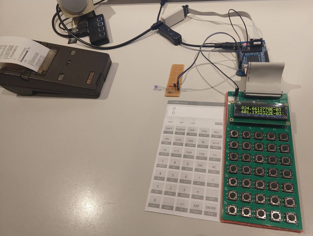
The HP 82240A/B is a small thermal printer that HP made for their calculator line starting in the 1980s. It receives data over infrared: it requires no cables, no connectors, just an IR LED pointed at the printer’s sensor. I had one at home and wanted the calculator to be able to print to it.
The protocol has a nickname in the HP community: “Red Eye,” after the red infrared LED on the calculator’s IR port. This protocol predates IrDA by about seven years: the Infrared Data Association was not founded until 1993 and did not publish its first standard until 1994. Red Eye and IrDA are not compatible: they use different bit encoding, different carrier frequency, different frame structure. Despite this, the same Red Eye protocol ran unchanged from the HP-18C (1986) through the HP-50g (a span of about 20 years and more than a dozen calculator models). That kind of longevity from a protocol designed in a hurry to ship with a new calculator line is either good engineering or good luck, and I suspect some of both.
Supporting it was a pure FPGA exercise, done on a crude test board with an IR LED wired to a GPIO pin. The first task was understanding the protocol.
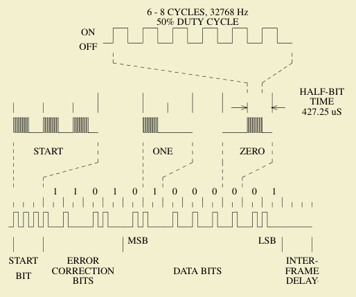
The HP 82240B Technical Interfacing Guide documents the frame format: each byte is sent as a 12-bit frame consisting of 4 error-correction bits followed by 8 data bits. Each bit is encoded as two half-bits: a 1 is transmitted as a pulse followed by silence (X_), a 0 as silence followed by a pulse (_X). A start sequence of 3 half-bit bursts precedes the data. The timing is derived from a ~32 kHz clock.
The error-correction nibble is computed from the data byte using a specific XOR pattern across individual bits: a simple but effective way to let the printer detect corrupted frames without a full CRC.
The SystemVerilog implementation is a five-state FSM: READY (waiting for a byte), START (sending the 3 half-bits start sequence), DATA and BIT (clocking out the 12 bits two half-bits at a time), and DELAY (inter-frame gap before the next byte). The busy output signal tells the CPU not to send another byte until the current frame is finished. To simplify my design, I use polling.
I debugged this on real hardware by watching actual waveforms on an oscilloscope. There are three test-point GPIO outputs in the design: the quarter-tick timing signal, the IR enable, and the raw IR LED output. With those three signals on the scope, I could see exactly what the FSM was doing at each stage and compare it against the protocol timing diagrams from the guide.
Getting the first printout from the HP printer (from a bare FPGA board with a loose LED wired onto a GPIO) confirmed the protocol implementation was correct. Yay! On to the next problem.
What Pathfinding Produced
At the end of this phase, the open questions had answers:
- Feasibility: yes,
tan,exp,ln, andsqrtare all computable from primitives. The algorithms work, and I also have an idea which algorithms should be used. - Key layout: several candidates tested and evaluated; working with some layouts feels better than with others.
- Number entry: the full input state machine, correct and tested, ready to port to assembly.
- Printer: a working IR protocol implementation, validated on hardware.
What comes next is making the arithmetic engine production-quality – a proper BCD implementation with full precision, guard digits, the CORDIC algorithm in depth, and thousands of test vectors. That is Post 3.