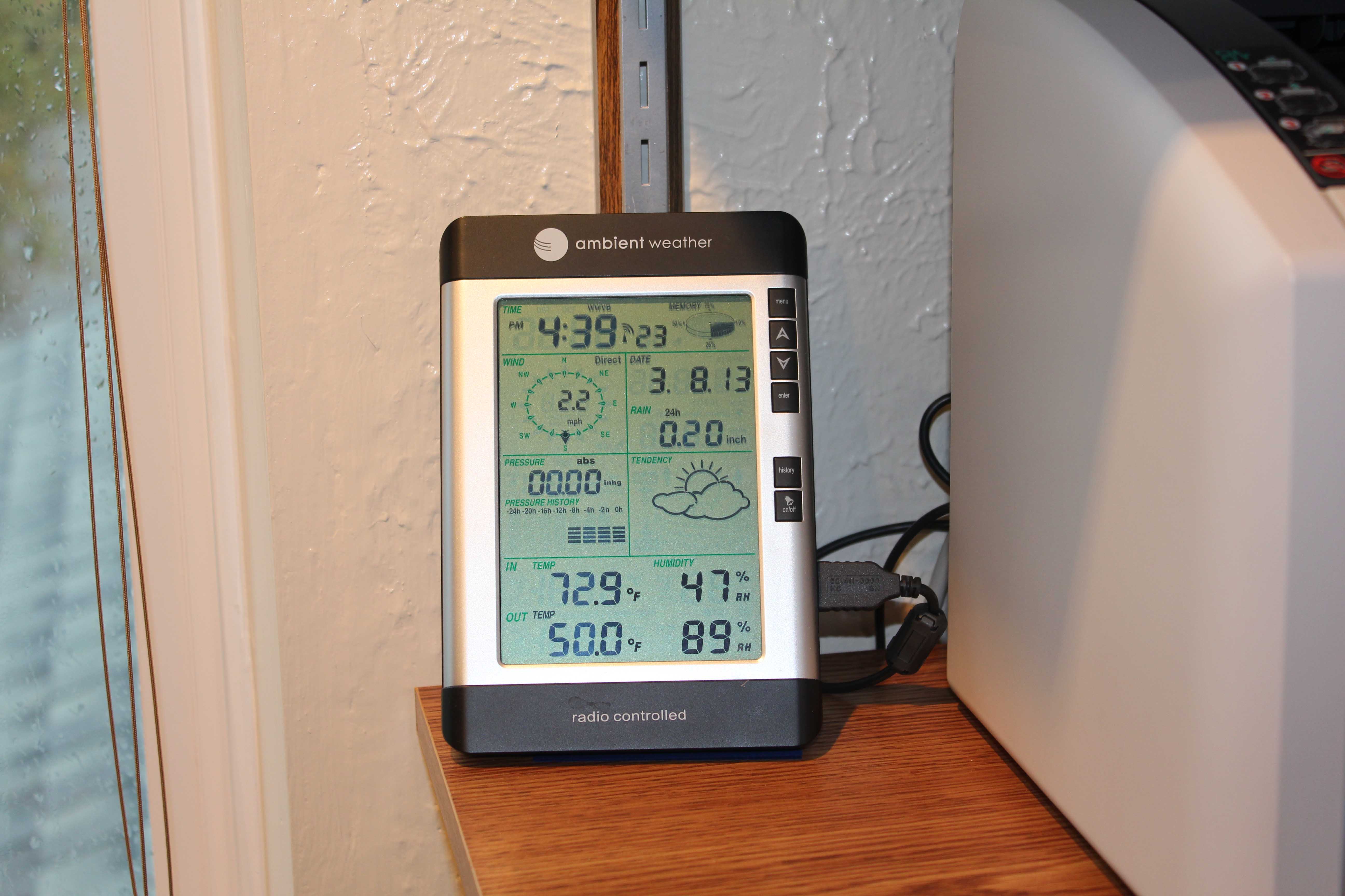
A weather station, Ambient Weather WS-2080 that I installed in my backyard has a receiver unit with a pretty nasty hardware issue: occasionally, its USB interface would hang hard. It could happen twice a week or once a month – it is very unpredictable and highly annoying. Once it happens, nothing short of a power reset of the receiver unit would fix it. You’d have to remove the battery or unplug the USB if you powered it through it. I’ve finally got around to fixing it. If you have a similar problem with that weather station, you may be interested to read on…
If this is happening to your unit, you will also know that in addition to the hang, the software that talks to it (“Cumuls” in this case), would also hang trying to read the USB data. This creates an additional problem: you would have to actively monitor the setup daily so you can fix it and not lose any weather data.
Instruments like that should be able to work autonomously for months, years at a time!
I wanted a robust and fully automatic solution since I tried almost anything suggested at various forums, but nothing worked.
My solution to this problem was a set of software scripts to detect when a device hangs and a small Arduino-based dongle board that controls the USB power to the receiver and can hard reset the unit when a problem is detected. As an additional bonus, I also wanted to get an email when the fault (and correction) happens.
Hardware
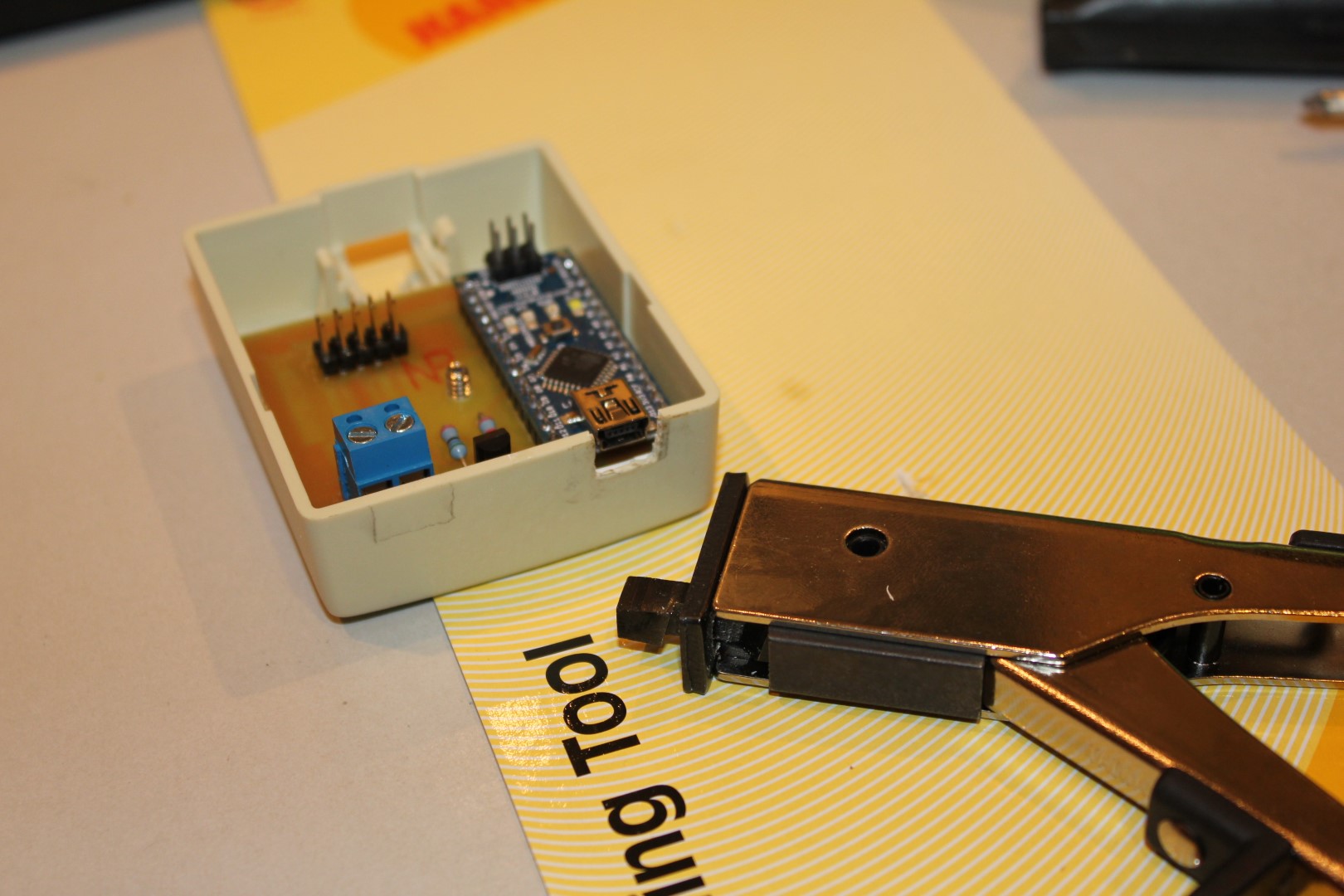
I used a spare Arduino Nano board and fitted it inside a small phone jack enclosure which I could then mount on the wall between the server PC and a weather station receiver.
The idea was for the server to talk to the Arduino via USB/serial and the Arduino would control a relay which would control the power of the USB connection to the receiver. The USB cable to the receiver would pass through this dongle.
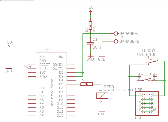
This is a final schematic done in the Eagle software:
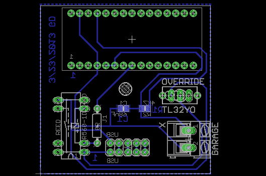
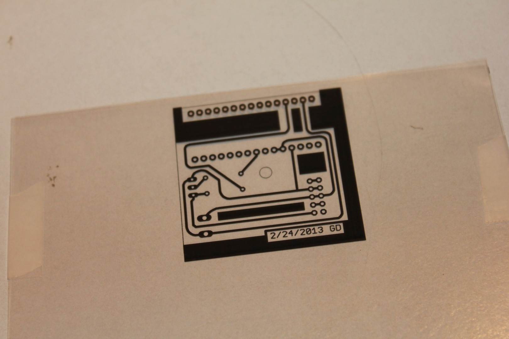
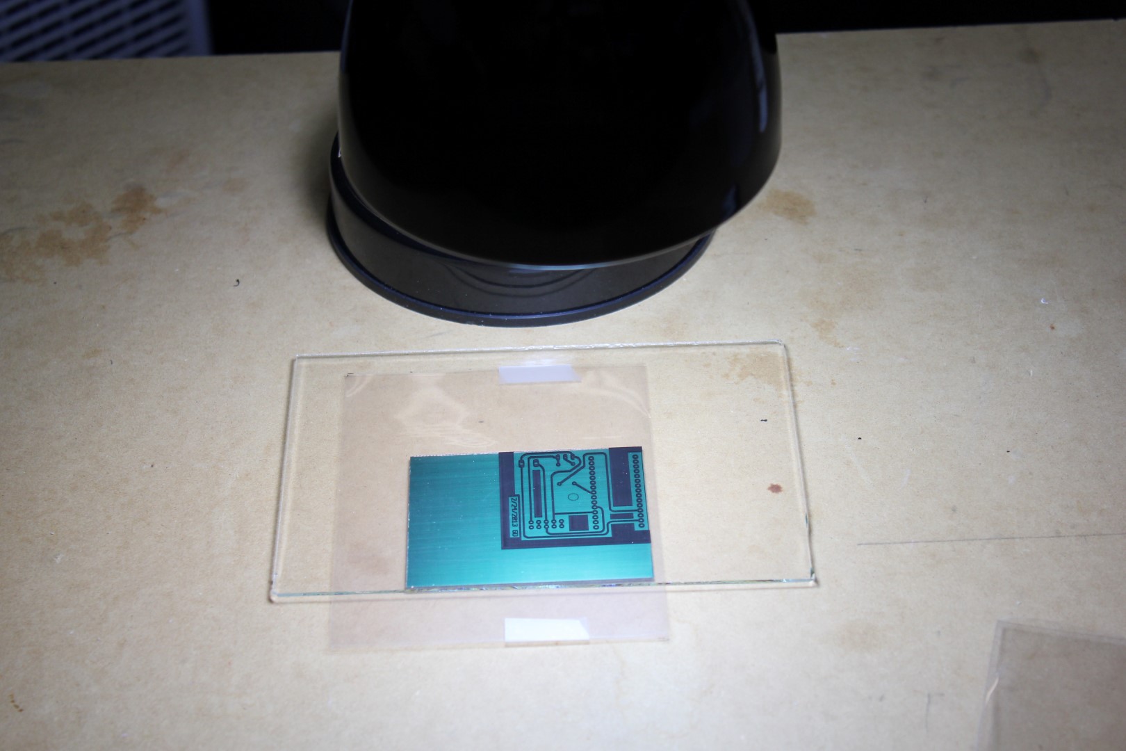
and the board layout:
The board also has a “garage door” terminal. This is hooked up to a switch on my garage door rail and detects when a garage is opened – a part of my home Internet-of-Things network. However, that’s a topic for another blog.
The 5×2 pin connector is a simple USB pass-through and the relay controls its +5V wire. All other USB signals are passed through unmodified.
This is the image of a finished board already fitted in the enclosure:

Once the board was ready, I mounted it on the wall. I want to thank my friend Brent who created a perfectly fitting (red) enclosure cover on his 3D printer for me!
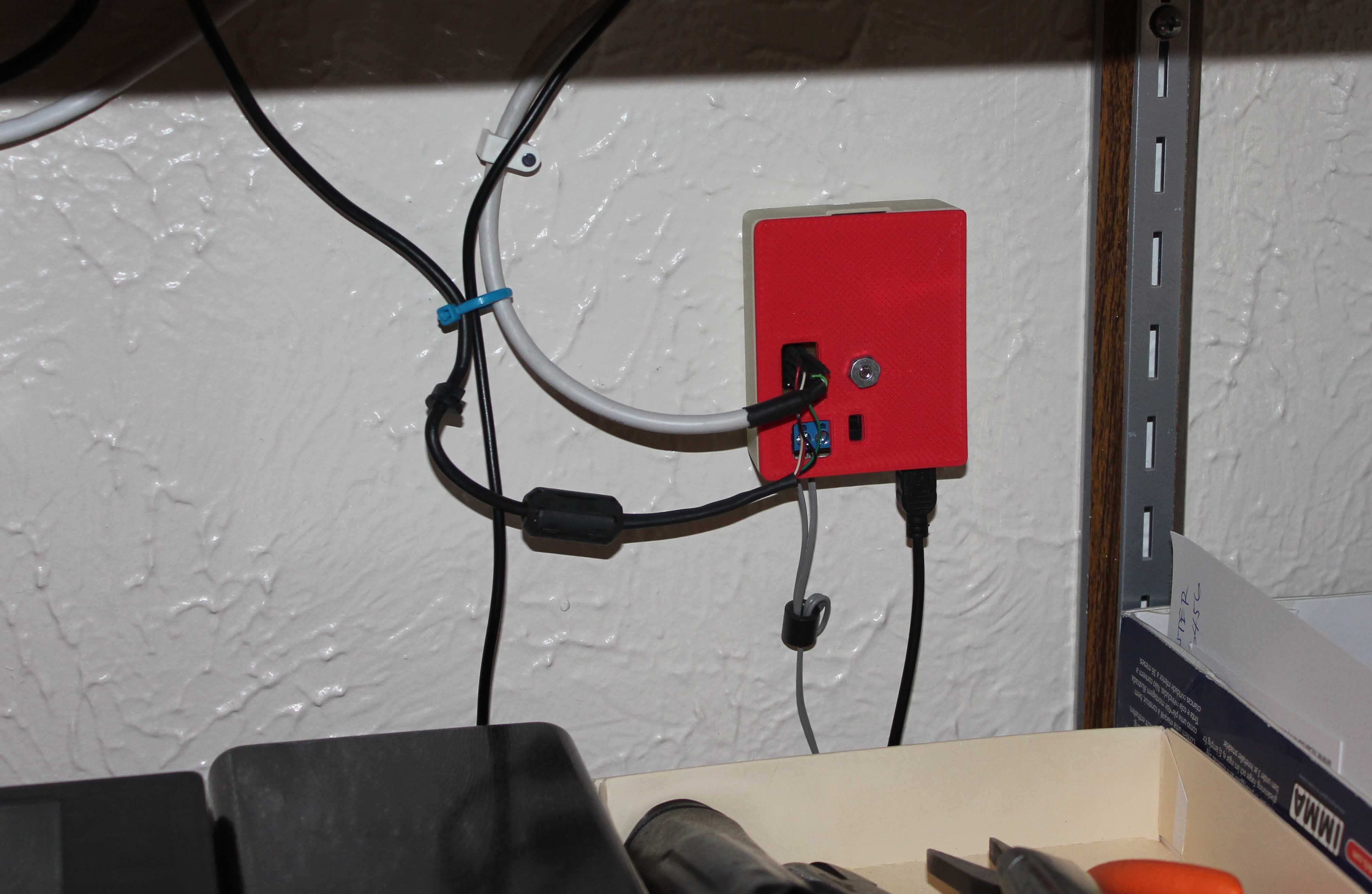
It is then connected to my weather station, whose USB power is now fully controlled by the server software through the pass-through dongle.
The board contains these parts:
Part     Value                          Device                         Package     Description
------   ---------------------------    ---------------------------    ---------   --------------------------
C1       68nF                           C-EUC0805                      C0805       CAPACITOR, European symbol
GARAGE   X                              AK300/2                        AK300/2     CONNECTOR
J1                                      0R                             0R/10       Bridge 0R 10mm
OVERRIDE TL32YO                         TL32YO                         TL3XYO      TINY SWITCH ON - MOM
R2       4K7                            R-EU_R0805                     R0805       RESISTOR, European symbol
REED     R560-1D.5-6D                   RR1A                           RR1A        RELAY
U$1      ARDUINONANO_V3.0_OPPOSITE_SIDE ARDUINONANO_V3.0_OPPOSITE_SIDE ARDUINONANO Arduino Nano V3.0
USB      USB                            PINHD-2X5_2.54                 2X05        PIN HEADER
A reed relay with an internal clamping diode from NTE Electronics is used. Its data sheet can be found here.
Software
This is the software that runs on the Arduino Nano board:
/*
 * 2/31/2013 version 1 (garage door switch only)
 * 4/4/2013  version 2 (added control to USB power)
 *
 * Digital pin 2 is connected to a switch to garage door. The return path
 * is to to 5Vcc and that voltage is read when the door remains closed.
 * This minimizes noise and false signals.
 *
 * Every time the switch toggles, serial outputs its new state:
 *
 *  Init
 *  G:0
 *  G:1
 *  G:0
 *  G:1
 * 1 means "Garage door opened"
 * 0 means "Garage door closed"
 *
 * Digital pin 5 is connected to a reed relay controlling the Power wire
 * of an external USB device. The (serial) input is monitored for a incoming
 * codes of '1' (turns the relay on) or '0' (turns the relay off). At the same
 * time the program will output 'I:'+code back to the serial to acknowledge
 * the reception. All other codes except '1' and '0' will be ignored.
 */
#include

#define PINSW               2       // Garage door switch on D2
#define PINUSB              5       // USB power of D5
#define PINLED              13      // Arduino built-in LED

Bounce bouncer = Bounce(PINSW, 200);

void report(int doorState)
{
    Serial.print("G:");
    Serial.println(doorState);

    // If the door is opened, turn on internal LED
    digitalWrite(PINLED, doorState? HIGH : LOW);
}

void loop()
{
    if (bouncer.update())
    {
        // Pin switch returns "0" when the door remains closed since it
        // completes a circuit from a +5V pullup to the ground.
        // When door opens, switch opens and breaks the loop, leaving
        // only the pull-up on the digital pin, so it returns "1"
        int value = bouncer.read();

        // Value = 1 when the garage door is opened
        report(value);
    }

    // Check if a byte is available from the serial port
    if (Serial.available() > 0)
    {
        int b = Serial.read();
        Serial.print("I:");
        Serial.println(b);
        if (b=='1')
            digitalWrite(PINUSB, HIGH);
        if (b=='0')
            digitalWrite(PINUSB, LOW);
    }
}

void setup()
{
    Serial.begin(115200);
    Serial.println("Init");

    pinMode(PINUSB, OUTPUT);
    digitalWrite(PINUSB, HIGH);

    pinMode(PINSW, INPUT);
    digitalWrite(PINSW, HIGH);

    pinMode(PINLED, OUTPUT);

    // Upon initialization, send the starting state
    int value = digitalRead(PINSW);
    report(!value);
}
Since I am using the same setup to detect garage doors being opened and closed, the source contains code to handle that task as well. As with anything else, you may want to just take the main ideas and create your own solutions.
The USB dongle is connected to a Windows Home Server 2011 box, so I made a couple of scripts in Windows PowerShell to monitor for the failure condition which can be identified by Cumulus software not saving its real-time report data file within some time (I selected 60 min). The script was added to the Task Scheduler to run every 1 hour:
C:\Windows\System32\WindowsPowerShell\v1.0\powershell.exe -File ServerAutomation\Watchdog\CheckTime.ps1
#
# Check the last modification time of a file and compare it to the current time
# If more than X minutes has passed, send email
#
$file = "C:\Cumulus\realtime.txt"

# If the Cumulus process is not running, do not check
$process = Get-Process Cumulus -ErrorAction silentlycontinue
if (!$process)
{
    exit
}

$date = Get-Date
$filedate = (Get-item $file).LastWriteTime
$diffdate = $date.Subtract($filedate)

function sendMail
{
    $EmailFrom = "[email protected]"
    $EmailTo = "[email protected]"
    $Subject = "Notification from Moria"
    $Body = "Cumulus: $file file did not update in 60 min! I will reset USB and restart Cumulus..."
    $SMTPServer = "smtp.gmail.com"
    $SMTPClient = New-Object Net.Mail.SmtpClient($SmtpServer, 587)
    $SMTPClient.EnableSsl = $true
    $SMTPClient.Credentials = New-Object System.Net.NetworkCredential("devic.home", "password");
    $SMTPClient.Send($EmailFrom, $EmailTo, $Subject, $Body)
}

$diffdate.TotalMinutes

if ($diffdate.TotalMinutes -ge 60)
{
    # Reset the USB by setting a trigger environment variable (see PostGarageDoorData.ps1)
    cd C:\Cumulus                           # Execute in Cumulus directory
    # Send a signal to reset the USB
    echo Y >> resetusb.txt
    kill -processname Cumulus               # Kill the Cumulus process
    sendMail                                # Send email while the USB is being reset
    sleep 30                                # Wait 30 sec: USB restart can take up to 15
    Start-Process Cumulus.exe               # Restart the Cumulus process
}
The script checks if that file has a timestamp older than 60 minutes, and if it does, it will set a signal (via an environment variable) to another script to reset the power on the USB dongle. At the same time it will also (1) send an email to notify me about the event and (2) reset Cumulus software. PowerShell makes doing all of that really easy.
I used a separate script to reset the USB since I am running some other processes that were combined with it. This is a part of that script that checks for the event and resets the USB:
$line = ""
$previous = "G:0"
[Environment]::SetEnvironmentVariable("RESETUSB", "N", "user")

# Post the initial state to zero out future graphs
C:\python27\python.exe post.py $previous

do
{
    try
    {
        $port = New-Object System.IO.Ports.SerialPort com4,115200,none
        # With a timeout, ReadLine() will cause repeated exceptions when
        # the input buffer is empty. Otherwise, it should wait until a
        # full line (with a \n !) is available
        $port.ReadTimeout = 10000        # 10 seconds
        $port.Open()
        $line = $port.ReadLine()
    }
    catch [TimeoutException]
    {
        Write-Host -NoNewline "."
    }
    finally
    {
        $port.Close()
    }

    # If the $line contains 'G:', send it to the email script
    if ($line.StartsWith("G:"))
    {
        # Post a previous state followed by the new state so they form a square signal
        C:\python27\python.exe post.py $previous
        C:\python27\python.exe post.py $line
        $previous = $line
        $line = ""
    }

    # Check for a request to reboot the USB device
    if (Test-Path("c:\Cumulus\resetusb.txt"))
    {
        del c:\Cumulus\resetusb.txt
        date
        date >> log.txt
        "Resetting the USB!"
        $port = New-Object System.IO.Ports.SerialPort com4,115200,none
        $port.Open()
        $port.Write("0");
        Start-Sleep(5)                    # Wait 5 seconds
        $port.Write("1");
        $port.Close();
    }

} while(1)
It was a satisfying moment when I first got the email from the system: It rebooted the receiver unit, the software and had reset the weather station. It all continued to work as if nothing had happened and you’d not know if you hadn’t checked the weather data and saw a few missing entries. Then I checked the Weather Underground feed and surely enough – a short flat-line of missing data was closely followed by new valid data and all that happened without my intervention.
This is a link to WeatherCloud where I post weather data. This is a RapidFire WU site where the weather conditions are updated every 5 seconds.
Finally, this is a hosted website containing weather data updated by the Cumulus software using one of the many available weather templates.
Backup images


on my ambient weather monter the tendency and humidity stop working i drop it
I have 2 receiving units and on one the internal pressure sensor stopped working. AW are entry level products for HWS purposes so I am ok with that.
When I reset my 2080 by holding the “up” button it fully resets. But when I remove power for 30 seconds it comes up with a bunch of bugus readings. Does your software somehow restore the last valid readings to the station?
No, the software (via a relay) simply cuts off the USB power for a few seconds and that resets the receiver. The data is lost – but not much of it since it figures out that the station is frozen rather quickly. Recently, these units started giving me some other problems (failed sensor readings etc.) so I am thinking of dumping the AW for something more reliable that should work more years without having to deal with issues like that.
Thank you for your reply. I have looked into Davis but they are frightfully expensive. I had LaCrosse before and that was not very good either. Lately my Ambient has gone into hang state within seconds of starting Cumulus. I guess it’s dead. Sigh….
I guess if either of us finds a reasonably priced unit that works properly we should spread the word.
Hello Goran, my name is Victor from Lima – Peru. I want to made this project, but I dont understand a few thinks.
First, could you bring me a total list of the electronic components?.
Second, the arduino Nano need a specific scketch to upload
Third, I understand that this module is connect between the WS2080 console and the PC, but how?
Thanks a lot for your time, best regards
Victor
Hi Victor,
I have updated the blog with Arduino source code and the BOM. The board has a 2×5 pin header connector marked “USB” which requires USB cable splicing: on the schematics you will see that pins 3-4, 5-6, 7-8 and 9-10 are tied together, so those signals are passed through, but 1-2 are separated by a reed relay. That is a USB power rail which is controlled by the relay. You will simply have to cut two USB cables (one leading to the PC and another one to the weather unit) and solder 1×4 .1″ pitch connectors on their ends being careful to follow the standard USB wiring lineup: 1=5V, 2=Data, 3=Data, 4=Ground. (Yes, the on-board connector has a spare pair of pins, it could have been 2×4 but I was planning to tie the ground twice, if needed.)
Hope that helps!
Sorry about the delay to answer you. Thanks a lot for your inputs. Best regards. Victor
Thank you so much for such an informative piece of information 🙂
If anyone interested similar one’s have a look here
“Ambient Weather WS-2902B WiFi Smart Weather Station”
Thanks