In this blog, I will show you how to interface an Atari-style joystick to the Altera DE1 FPGA board running a Spectrum implementation, how to change the ROM to enable you to input some game-cheat pokes, and a few games I eventually completed using this setup.
Although this article revolves around my particular ZX Spectrum implementation, the code and ideas are applicable to all similar setups.
I went through my formative years playing (and eventually disassembling and hacking) Spectrum games. Thanks to a friend whose brother in Germany was supplying an incessant stream of games for the machine, I had the privilege of checking out most of them and picking only the best ones to play. Perhaps such a flood of games made me bored with gaming and more curious about software design, programming, and computer design, all of which eventually became my life-long profession and a hobby. I am sure ours is a whole generation impacted in a similar way.

Those early games were creative: they required planning, strategy, and exploration instead of relying on a joystick action and a fast button tapping alone. Many of those games had puzzles to be solved, labyrinths explored and large unseen maps navigated and discovered. It is no surprise that even now, 30 years later, there is still a large number of Spectrum enthusiasts and fans playing those games and even writing new ones.
Today, these retro games could be found in many places on the web. Their bits and bytes have been processed into various file formats suitable to load directly into one of many software simulators or dedicated retro hardware boards. The files can still be used to recreate the original sounds which could then be loaded into real Spectrums or FPGA boards.
Since I wanted to load games into my Spectrum FPGA design in this old, retro way, I have written an Android app with a built-in large database of games (more than 10,000). Games can be rated, searched for, downloaded, and played as originally intended – through a high-pitch buzzing sound. Connect an Android device to your Speccy or FPGA board, press LOAD “” and sit back to enjoy the show.
You can pick up the free PlayZX Android app here.
Clearly not suited to everyone’s patience limits (there are many faster ways to load games, for example, use a DivIDE interface), loading a game this way keeps evoking those childhood memories, re-enacting that excitement of seeing and hearing a game being loaded, watching the screen border dancing in colors. Various parts of a game, having different tones, release that magic and wonder of what exactly is being loaded: screen image (easy to spot), sprites and maps (have a regular beat to it), or code (sudden jumble of pattern-less sound noise).
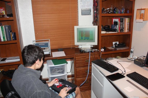
ZX Spectrum ROM
ZX Spectrum ROM was written by Dr. Steve Vickers when he was 29 years of age. Compact in design (fits in 16K), it implements a substantial version of ANSI BASIC including floating-point arithmetic, trigonometric functions, and all necessary system routines.
Dr. Vickers wrote the entire code in assembly language, on paper, with a pencil.[i] The code was assembled on a Zilog ZDS-1 system using Zilog’s assembler. [ii]
It has been disassembled and commented on, line by line, in the book “Complete Spectrum ROM Dissasembly” [iii] One can learn a lot by studying that code and reading the comments.
As an example, its internal powerful calculator routines were Forth-like, stack-based which subsequently became the cornerstone of Steve’s next venture – a somewhat odd “Jupiter-ACE” personal computer. Instead of BASIC, it used Forth, a language better suited to how Steve perceived computing (he was a mathematician and a computer scientist). Eventually, it did not fare well in the increasingly crowded market where BASIC started to be the expected norm.
For those interested, this wiki page has a nice history on the Spectrum BASIC: http://faqwiki.zxnet.co.uk/wiki/Sinclair_BASIC_history
The ROM, modified
Game cheats are usually limited to giving a player an unlimited number of lives or making his character invincible. That is done by modifying one or more bytes in the program memory after a game has been loaded. Most software simulators provide an option to stop the simulation and modify memory, thus applying the cheats. On an FPGA solution, the situation is a bit trickier since the board cannot be easily stopped. A solution I used in this hack was to modify the ROM in such a way that it lets the user break and enter a cheat using normal keyboard input methods, all while the FPGA/Spectrum is running. As such, it is independent of the platform it is running on: this solution could as well be used on real Spectrum hardware with such modified ROM and an added NMI button.
An NMI (non-maskable, means it can not be disabled in software) interrupt pin, when asserted, causes the Z80 to issue a call to the address 0x66 which is in the ROM. At that address, the code is patched to jump to our custom handler which is placed high in the ROM address space at some spare locations normally not used by any code. These bytes all contain 0xFF.
This is the handler code:
; ---------------------
; THE 'SPARE' LOCATIONS
; ---------------------

;; spare
L386E:  DEFB    $FF, $FF        ;

; ----------------------------------------------------------------------------
; This custom NMI handler provides a way to enter a POKE for a game by typing in
; the address (5 decimal digits) followed by the value (3 decimal digits)
; after which the value will be stored to the selected location.
; ----------------------------------------------------------------------------
nmi_handler:                    ; NMI handler
        push    bc
        push    de
        push    ix
        ld      hl,$04000       ; Use the screen memory as a temp storage
        ld      e,$08           ; Will load 8 characters (numbers)
next_key:
        ld      bc,$f7fe        ; Number row 1..5
        in      a,(c)
        ld      c,a
        ld      a,$01           ; Preload 1
        bit     0,c             ; If the key has been pressed
        jr      z,accept_key    ; Accept it
        inc     a               ; Preload 2
        bit     1,c             ; and continue for every key up to 5
        jr      z,accept_key
        inc     a
        bit     2,c
        jr      z,accept_key
        inc     a
        bit     3,c
        jr      z,accept_key
        inc     a
        bit     4,c
        jr      z,accept_key
        ld      bc,$effe        ; Number row 6...0
        in      a,(c)
        ld      c,a
        ld      a,$06
        bit     4,c
        jr      z,accept_key
        inc     a
        bit     3,c
        jr      z,accept_key
        inc     a
        bit     2,c
        jr      z,accept_key
        inc     a
        bit     1,c
        jr      z,accept_key
        xor     a
        bit     0,c
        jr      z,accept_key
        jp      next_key
accept_key:
        ld      (hl),a          ; Store current key value into the buffer
        inc     hl
poll_key_release:               ; Poll for any pressed key to be released
        ld      bc,$f7fe
        in      a,(c)
        cpl
        and     $1f
        jr      nz,poll_key_release
        ld      bc,$effe
        in      a,(c)
        cpl
        and     $1f
        jr      nz,poll_key_release
        dec     e               ; Decrement the number of keys expected
        jr      nz,next_key     ; Jump back to accept next key if not yet done
        ld      ix,$4000
        ld      b,$05           ; First 5 numbers represent the address to POKE to
        call    decimal_to_hl
        push    hl              ; Address is in HL, store it
        ld      b,$03           ; Next 3 numbers represent the value to POKE
        call    decimal_to_hl
        ld      a,l             ; Value is in L
        pop     hl              ; Get the address
        ld      (hl),a          ; POKE a value
        pop     ix
        pop     de
        pop     bc
        pop     hl
        pop     af
        retn
; Read a decimal value pointed to by IX register
; The number of digits is given in B register
; Return the value in HL register
decimal_to_hl:
        ld      hl,$0000        ; Start with value of 0
lp2:
        push    bc
        ld      b,$09           ; Multiply the current value by 10
        push    hl
        pop     de
lp1:
        add     hl,de
        djnz    lp1
        pop     bc
        ld      e,(ix+0)        ; Read in the next digit
        ld      d,$00
        add     hl,de           ; Add in the new value
        inc     ix
        djnz    lp2             ; Loop for the requested number of digits
        ret
The handler code reads the keyboard port and polls for exactly 8 number keys to be typed in: the first 5 digits represent the address and the next 3 digits represent a value to be set to that address. The address can reasonably be anything from 16384 to 65535 (decimal), although the code will let you input any number (a nice feature allows you to type 00000, or any address in the ROM if you had accidentally pressed the NMI button without really wanting to modify a value). A value itself can range from 000 to 256 (decimal).
After 8 digits have been read, they are processed into machine code address and value pairs after which the value is being set, or “POKE’d”, to the given address, and the control is returned to the interrupted game.
The routine is using the first line of the screen as temporary buffer storage, so as you type the numbers, you may see a line of “garbage” (as you can see below in the screenshot of Sabre Wulf while it is being poked with a cheat code).
The A-Z80 project has the updated files (both on the OpenCores and GitHub): you will find changes in the ZX Spectrum host folder both as a source and a compiled ROM binary which you can use in your own project.
Let’s Go Gaming
There are several places on the web that list a large number of POKEs, cheats, and maps. My favorite is The Tipshop (http://www.the-tipshop.co.uk).
3D Deathchase
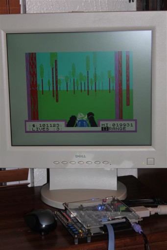
POKE: 26463, 0 for infinite lives
After increasingly difficult levels, the game wraps around. I have stopped playing it after exceeding a score of 100,000.
Sabre Wulf
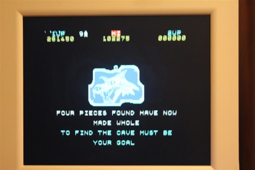
Here is the final screen which they show you once you complete the game:
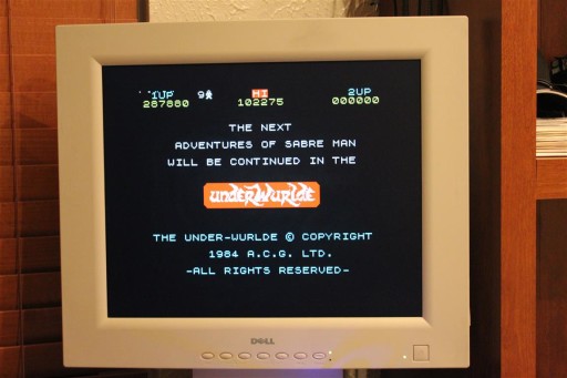
POKE: 43575, 0 for infinite lives
A question might be raised: what’s the point of cheating in a game in order to complete it? Does not that defy the purpose of playing it or take from the enjoyment of accomplishment?
Most of us do not have much free time to dedicate to master games we once loved to play. This way, we can finally have them completed. For me, it also satisfies the curiosity I had about what happens at the end of a game and how it feels to have it finished. Yes, I could have always simply looked it up on YouTube, but actually working through games myself provided satisfaction and a certain sense of closure.
Atari Joystick
In my previous blog, I described a modification of a Bluetooth game joystick that connects to the Altera DE1 FPGA board. In the meantime, I’ve found an old-style Atari joystick in a Goodwill store which I just could not pass on. It has only a single button but a very convenient 9-pin RS232 connector. (Although there are 2 physical buttons, only one can be selected at a time using a switch on the base.)
The joystick’s connector can easily be bridged by a standard 9-pin internal cable used in PC motherboards:
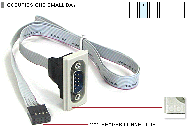
Connect the other end, 2X5 header connector, directly onto the FPGA GPIO pins.
The joystick exports 5 signals: 4 directional and one from a fire button, and has a common ground pin. Pull-up resistors are not needed since Altera FPGA GPIO pins already have built-in pull-ups which should be enabled with this configuration line:
set_instance_assignment -name WEAK_PULL_UP_RESISTOR ON -to MyPin
This picture shows the Joystick attached to the Altera DE1 board using that cable:
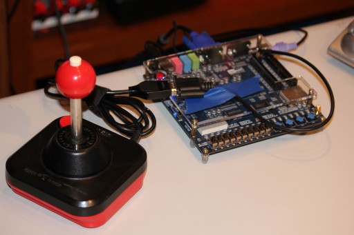
The 2×4 header plugs in nicely to one end of a GPIO connector.
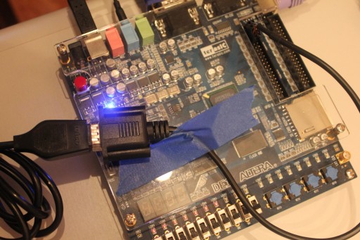
In the Altera Quartus project, you would define GPIO pins like this:
###########################################################################
# GPIO-0 Expansion Header 1
###########################################################################
set_location_assignment PIN_A13 -to kempston_gnd
set_location_assignment PIN_B13 -to GPIO_0[1]
set_location_assignment PIN_A14 -to kempston[4]
set_location_assignment PIN_B14 -to GPIO_0[3]
set_location_assignment PIN_A15 -to kempston[3]
set_location_assignment PIN_B15 -to kempston[2]
set_location_assignment PIN_A16 -to kempston[1]
set_location_assignment PIN_B16 -to kempston[0]
set_instance_assignment -name IO_STANDARD LVTTL -to kempston_gnd
set_instance_assignment -name IO_STANDARD LVTTL -to GPIO_0[1]
set_instance_assignment -name WEAK_PULL_UP_RESISTOR ON -to kempston[4]
set_instance_assignment -name IO_STANDARD LVTTL -to GPIO_0[3]
set_instance_assignment -name WEAK_PULL_UP_RESISTOR ON -to kempston[3]
set_instance_assignment -name WEAK_PULL_UP_RESISTOR ON -to kempston[2]
set_instance_assignment -name WEAK_PULL_UP_RESISTOR ON -to kempston[1]
set_instance_assignment -name WEAK_PULL_UP_RESISTOR ON -to kempston[0]
Lastly, define those ports in the Verilog code:
module zxspectrum_board
( ...
//-------- Atari joystick mapped as Kempston
input wire [4:0] kempston, // Input with weak pull-up
output wire kempston_gnd, // Helps mapping to DB9 cable
...
Your particular connector (and joystick pin assignment) may be slightly different, always use common sense and check before connecting.
Notes:
[i] https://groups.google.com/forum/comp.sys.sinclair
[ii] You can read more on the ZDS-1 development system here:
http://archive.computerhistory.org/resources/Zilog/102646173.pdf


Great article(s). Greetings and many thanks.
ciao Goran !
Ho anche io una Altera DE1, sono riuscito a ampliare la tastiera sul progetto di Mike Stirling con i tasti extra come da tuo sorgente “zx_kbd.sv” ma non riesco ad implementare il joystick kemston del quale ho realizzato una board su GPIO1
https://web.archive.org/web/20230609203448/https://www.mike-stirling.com/retro-fpga/zx-spectrum-on-an-fpga/
mi puoi aiutare?
Grazie
Domenico