


I got hold of an old Sinclair ZX81 in apparently good and working condition!
ZX81 was the first personal computer I owned. I was 13 years old. At that time, I copied its 8K ROM, byte by byte, into a notebook, and hand-disassembled it (a consequence of which I still suffer from: I still remember some Z80 opcodes), but I never opened it. Finally, now I can do what I missed 🙂
This post shows how it generates TV images and how its Z80 CPU boots. I instrumented it and captured scope and logic analyzer images as it was powering on.
What a beauty!
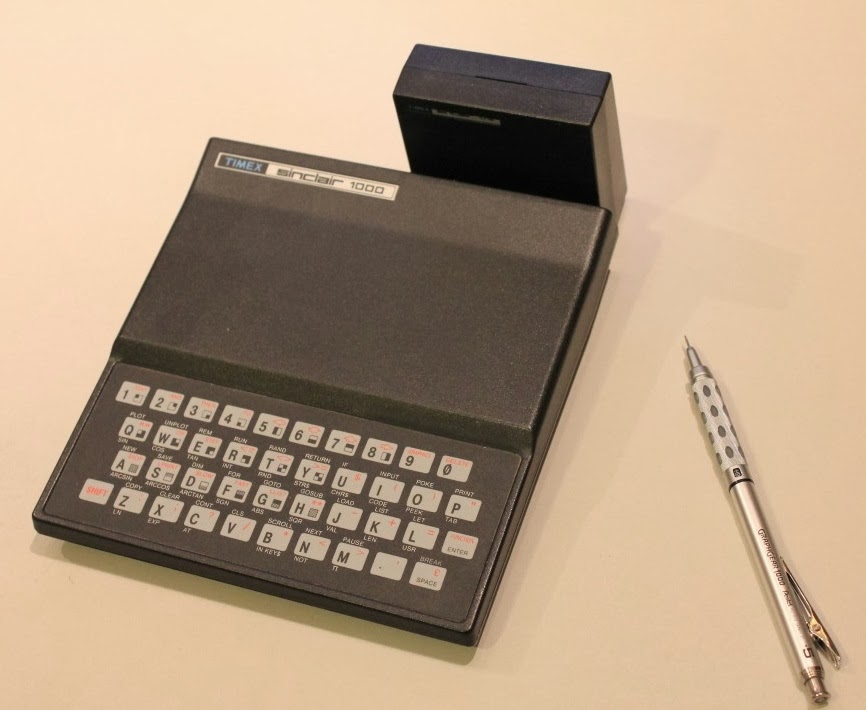
Actually, this is the US model branded as “Timex”. European models were slightly different.
First, I tried to connect it to our TV in the living room over the VHF channel 2 or 3. It did not work. Perhaps the signal was too weak or the modulator was not working? The TV showed a different kind of noise when the computer was plugged in, so I knew ZX81 did work and generated something on its TV-out.
ZX81 had only one TV-out connector and that’s coming out from a modulator. Modulator embeds (well, modulates) input signal within a specific frequency that corresponds to standard TV channel 2 or 3. The signal coming into the modulator box should be a nice composite-level TV signal.
This simple trick sometimes works: I hooked up a composite cable to the modulator’s input pin and then connected it to my TV composite input. Shout, that did not work either. Perhaps the signal levels are too low or the signal is of poor quality so the TV refuses to sync.
It’s time to bring in heavy guns.
I connected the composite signal to my Rigol scope, turned it on, and captured some signals. They looked quite nice, actually. Rigol can arm the capture at a certain video line. I was not expecting to be using that feature ever, but here it is, and it is very handy!
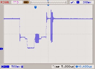
Here is an image of one video line (forgot which one) captured by the scope:
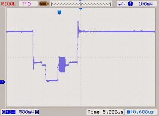
You can clearly see the horizontal sync signal followed by a color burst data and then a line of the picture – all white, which is “high” level.
Now, if I just had another TV…!
A quick trip to a high-tech Goodwill here in town found me a nice, working, old-style TV for just $7 !!! People are throwing these things out since in the US all over-the-air broadcasts switched from analog to digital. What a steal!
I connected it and without any fuss this time, it worked – there was an image shown nicely on that old TV (through the composite signal):
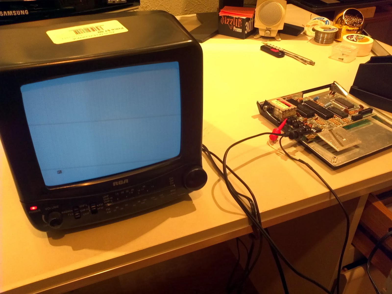
There on the bottom of a TV screen, you can see ZX81’s legendary [K] prompt!
I wanted to complete that “picture” and capture the actual line containing the [K] prompt. Back to the Rigol scope and selecting one of the lines towards the end of the image:
There is was – a burst of black just as the line starts to unroll.
The next thing I always wanted to see is Z80 CPU booting. Here I need to diverge a bit from this topic and tell you about our high school – a really good vocationally oriented technical school “Rudjer Boskovic” in Zagreb, Croatia. I was on a computer engineering track and we had to actually do something concrete as the final practical work. A few of us got together and made an actual simple Z80-based computer and connect it to a relay. The objective was for it to ring the school bell every period. The tools were primitive and it never really worked, although we would swear that we’ve seen some current passing through it at some point. Perhaps that was the magic smoke going out. We never found out: we did not even have an oscilloscope!
Ever since that time I wanted to see Z80 booting up!
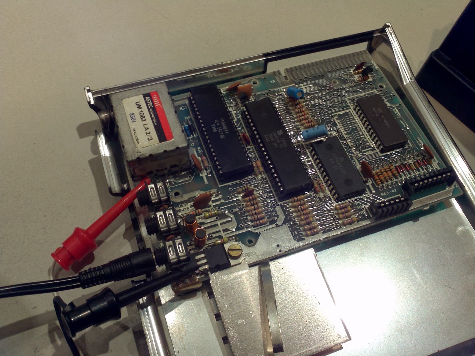
Here comes into play a logic analyzer: with 16 channels and probes that could be easily hooked to large DIP pins of a Z80 in its socket, I selected data bus (D0-D7), read enable, reset pins, and as many address lines as I have probes left.
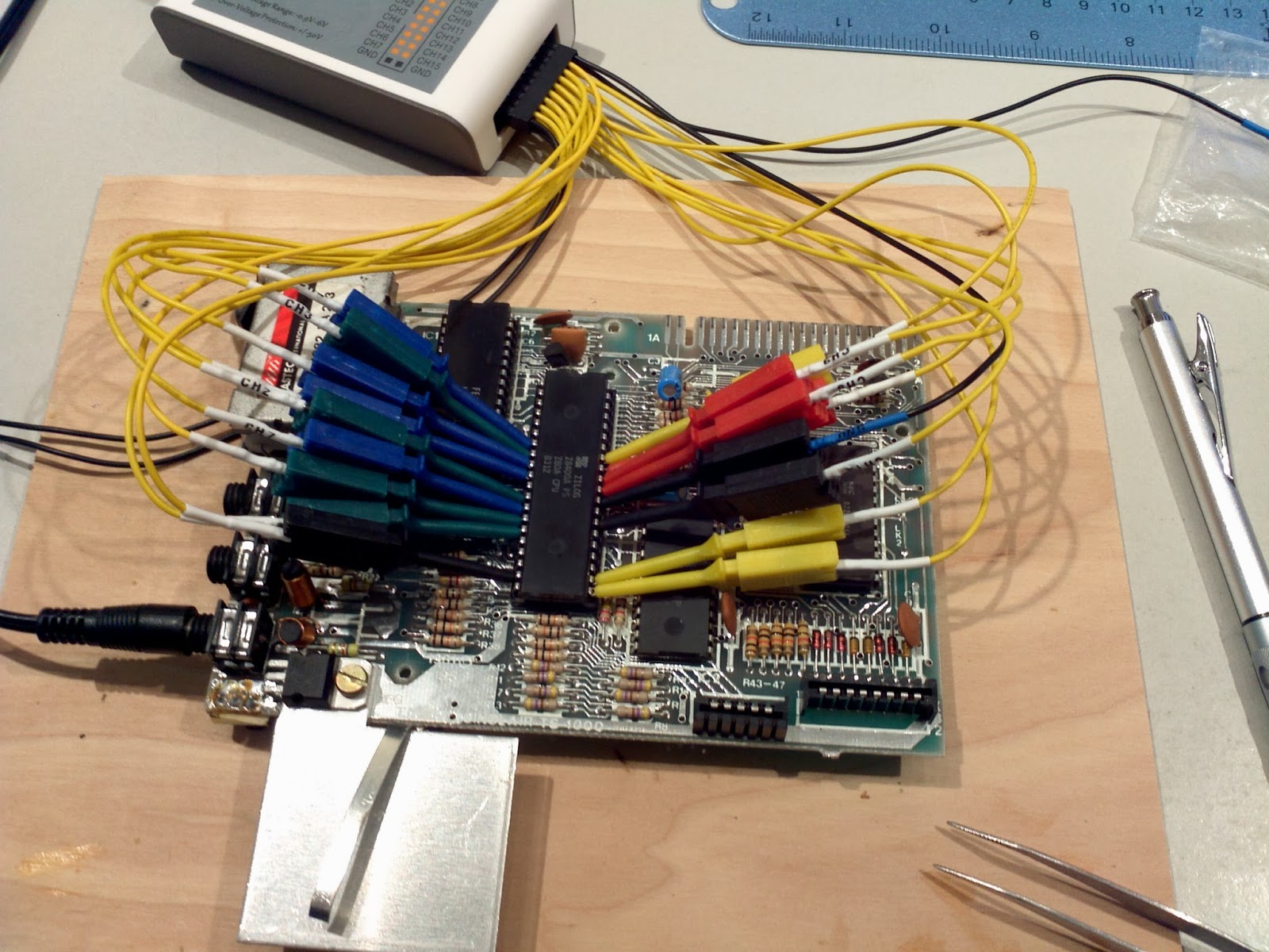
Finally – here is an image of Z80 pins dancing happily through the power-up sequence:
Since this is so exciting (well, not quite for everyone), let’s dissect what’s going on in more detail.
When Z80 boots, it starts fetching and executing the code at address 0. That address is in ROM. I have the ROM image as a file – you can find all those ROM images out there – and opening it up with my favorite hex editor shows the first few bytes:
The start of ROM contains these bytes: D3, FD, 01, FF, …
If you disassemble them into human-readable language, they represent these instructions:
|
1 2 |
out (0xFD), a ld bc, 0x7FFF |
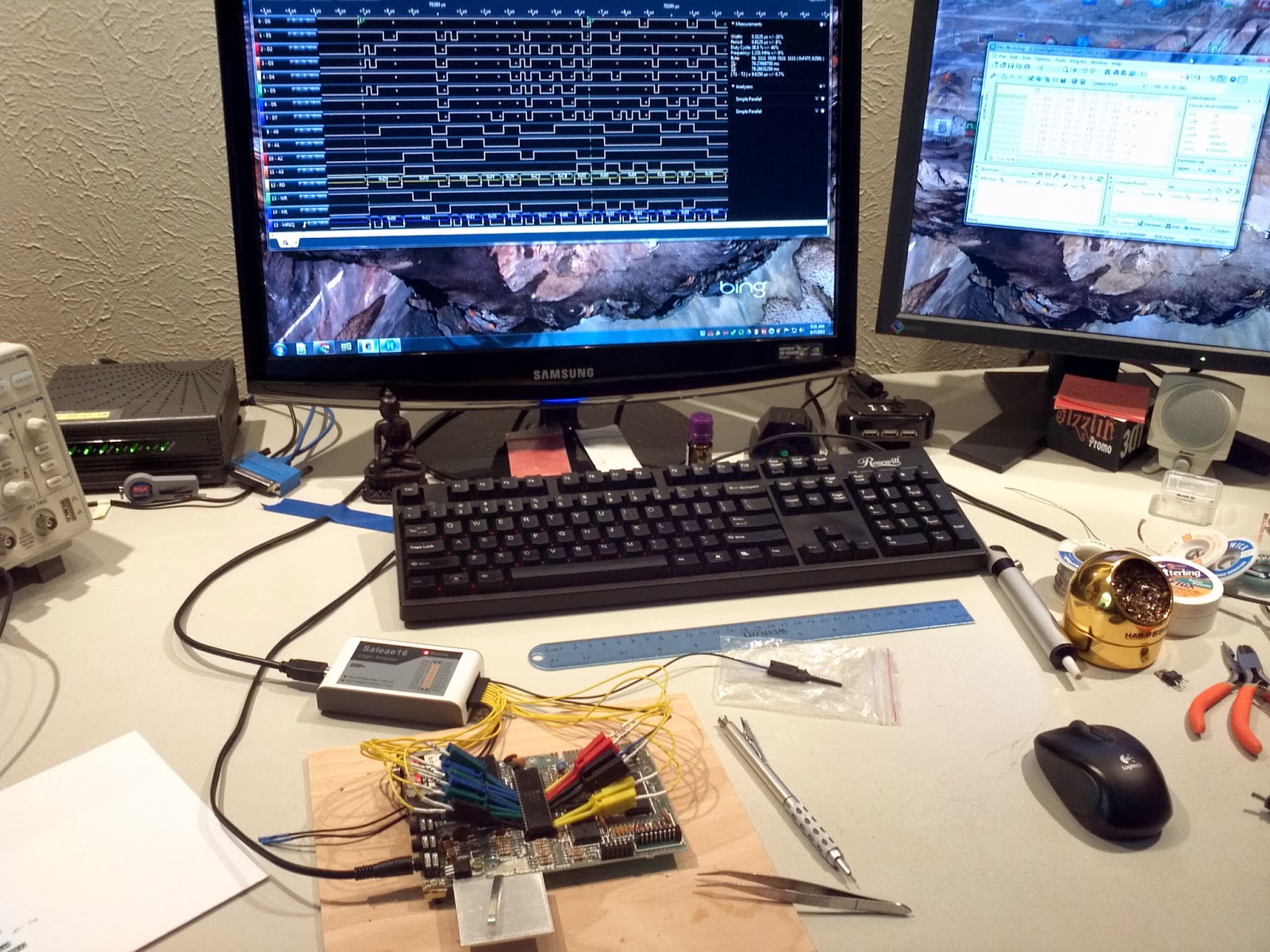
Let’s see what Z80 is doing – the next image shows what’s on its pins when it powers up; the red arrow points to a decoded data bus. It is fetching instructions from the start of ROM as expected (hello?):
The software decoder built into the analyzer application shows these bytes: D3, FD, 01, FF, …
Now, that was fun! 🙂
channel 2 or 3 on analogue TV is on VHF-low band, not UHF.
Thank you for the correction!
Wauw Nice ! Webpage
I own a ZXSpectrum and build ones a Micheal Knight KIT led application
in Machine Code with only a z80 cpu and rom, and z80 instruction book.
Did not have measurement equipment then.
People ask me then, will it work ! It does !
Thanks for all the info on your webpage, interesting !
I am interested again in the Z80, I will boot it ! after 30 years.
Named it back then, my SBC single board computer, because it fitted
on a single Eurocard print format.