The software I use to create board schematics and layouts is Eagle CAD.
Software-wise, I also use git version control: I frequently version and commit all changes to project files and then upload them to a cloud server. I like GitHub and BitBucket servers which are free. My suggestion is to always version your work and to always backs it up.
There are a number of great tutorials on the web about using Eagle and git, so I will not go into it here.
It is really useful to have parts in front of you when you start doing the schematics. Unless you will be ordering directly from your BOM (“Bill of Materials” – a list of parts used on the board), you may select components to match those you have on hand.
Often you will have to “create” a part yourself since it is not in the Eagle library. Eagle has a number of 3rd party libraries which you could download and use. They all cover thousands, nay, millions of parts, which brings me to one frustrating side of Eagle: finding parts in the library.
Searching for parts and matching the correct footprint normally takes me a long time. Eventually, I started creating my own growing library of parts containing those that I own or have previously used so I can quickly refer to them. This significantly speeds up the process.
This web page has a nice Eagle part search which I use quite frequently:
http://www.esawdust.com/blog/eagle/eaglepartsearch.php
I recommend downloading and getting familiar with as many 3rd party libraries as you can to avoid recreating parts once you need them. There are several good libraries that are smaller and contain the most commonly used parts. SparkFun has a very good extended guide on the topic:
https://www.sparkfun.com/tutorials/108
If you are new to it, I would recommend reading through their tutorial.
The best way to learn is to study other people’s examples and schematics and if there is anything you don’t understand or don’t know how to do, deep dive into it until it becomes obvious. There are a lot of great open-source examples to learn from; for example, a good one is Spark Core:
https://github.com/spark/core
Everyone is different and the method that works for me when I am diving into a new area is to search for tips and tricks, especially advanced ones, quite early in the learning process. That way I assimilate simple things automatically by trying to understand complicated ones within the larger conceptual framework.
Start an Eagle project by creating a Project and adding a description in the Eagle’s Control Panel.
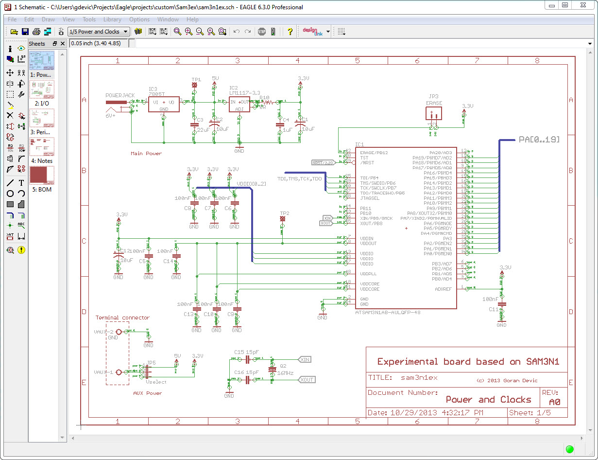
Always create a schematic frame first (frames-library.lbr) and position it to (0,0) coordinates (depicted by the black cross.) The frame will determine the paper size if you decide to print it, so choose a letter-sized frame. Frames also have coordinates along the edges which are used when pins and busses connect to different pages. There is also a nice summary box on the frame’s bottom where you can add the project name, date, and the likes.
If you want to, you could draw your own frame (command, “frame”).
Create and always have an open board layout window to check parts as you add them, but don’t attempt any routing at this time. Do not close that window since it would break the annotations with the schematics. Always open and close both at the same time but not through each window’s close button; use the list of projects in the Control Panel since that will keep them synchronized.
Eagle contains a number of custom scripts. I’ve found the most useful ones to be:
“length-freq-ri.ulp” calculate max frequency, current for each wire
“statistic-copper-plane.ulp” gives you area of copper vs. the board
“statistic-sch.ulp” displays a nice part statistics
Other useful commands are:
“run find <part or pin>” will find that part or pin and zoom on it.
Frequently click on the eye icon (“show”) to see all connected nets. Run the electrical rule check and make sure there are no errors. If you decide to let a few warnings though, be absolutely sure what you are doing before you approve them. Eagle is usually right when reporting them. In fact, in making this board I made a major mistake by letting some ERC warnings through while they showed a legitimate problem: on the schematics wires appeared connected while on the board layout they were not.
Once you are sure you have your final schematics, you can move on to layout.
Tools: Eagle CAD software (http://www.cadsoftusa.com); git version control (http://git-scm.com)