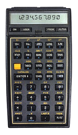
The idea for this project came about during a week in February 2021 when the power grid failed here in Austin, Texas. The government’s handling of the situation was, sadly, memorable. With a gas fireplace as the only source of heat and light, and a weak phone data connection as the only link to the outside world, I had a few days to think about something new and exciting to do. I picked up my HP-41CV and started pressing its buttons. As always, it felt good. I suddenly wanted to create something like that myself!
When I was in elementary school, I got a chance to see and play with one HP-41CV. I saw it loading a program from a magnetic tape and running it. The buzz of the card reader, along with the tiny magnetic strip getting pulled into the machine on one end, and exiting on another, followed by the calculator suddenly changing its responses, deeply impacted me as a child. Little did I know that it would also reshape the rest of my life. A few years later I got a Sinclair ZX81, and then ZX Spectrum, hacking with HiSoft Devpac MONS disassembler various games. Those two devices (the HP calculator and the Sinclair micros) directed me toward engineering, software, the inside of things. I spent my career as an engineer in large extent because of that.
A while back I looked at the Z80 chip itself. I re-made it as A-Z80 and also created a visual tool that runs its netlist, Z80 Explorer. That was, in some way, a closure on the Sinclair obsession. This calculator project feels like a similar closure on the HP part. This is not a clone, not an emulation, but a ground-up reimplementation of the same set of ideas. I wanted to understand from the inside out why these machines worked the way they did.
How does a scientific calculator actually work? Not in the hand-waving sense of “it has a chip and some buttons,” but all the way down. How does it store numbers? What algorithm computes sin(x)? How its very simple CPU operates?
This series documents getting those answers: the final product being a fully working scientific calculator designed and built from scratch, with a custom CPU created in an FPGA, hand-written microcode, C++ reference implementations providing golden reference values, and the physical hardware that sits on my desk and can calculate precise answers. It is all open source: you can see it; you can try it.
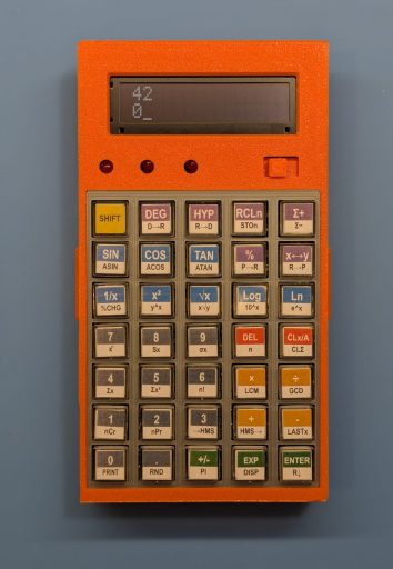
As far as I know, this project is very unique: I am not aware of any other scientific calculator (with this level of functionality) being implemented in FPGA using a custom CPU and the original, hand-written software to run it.
The Rules
One of the first things I settled on was what “from scratch” means for this project. The rules I set for myself:
- No pre-existing CPU. Real men create their own CPUs. 🙂 The processor is custom, designed in SystemVerilog and implemented in an FPGA.
- No floating-point libraries or specialized IPs. All arithmetic is BCD (binary-coded decimal), built from primitive nibble operations up.
- No emulated ROM. The calculator behavior is entirely in hand-written assembly code, not copied from any existing calculator.
- No shortcuts on precision. Every algorithm is verified against a C++ reference implementation with test vectors, not eyeballed.
The FPGA choice deserves a word. I could have built this around an existing RISC, ARM or another off-the-shelf CPU, using an SoC and writing code in comfortable C++, but there are many such implementations you can find around. That’s nothing new; that’s not even that hard to do. But using an FPGA means the CPU itself is my design: I specify the instruction set, the register file, the ALU operations, and every detail of how the machine executes via custom microcode. That is where the pleasure of creation lives.
The Decisions
BCD vs. binary floating point. Pocket calculators have traditionally used binary-coded decimals, where each digit is stored as a 4-bit nibble. The HP-35, the HP-41, the HP-15C: all BCD machines. BCD gives exact decimal representation at the cost of more complex arithmetic. Binary floating point (IEEE 754) cannot exactly represent many decimal fractions. For a calculator, BCD is the right choice. This calculator internally uses 16 BCD digits of mantissa (more than any HP calculator and enough to stay correctly rounded to the last displayed digit). Each mantissa has a corresponding 2-digit BCD exponent for the total magnitude range of 1.0e-99 to 9.999999999999999e+99 (there are no “denormalized” numbers).
RPN vs. algebraic. RPN (Reverse Polish Notation) means you enter operands before operators. To add 3 and 4, you press 3 ENTER 4 +. There are no parentheses, no operator precedence, and no “=” key. Instead, there is a four-level stack (X, Y, Z, T) that holds intermediate results. HP calculators have used RPN since the HP-35 in 1972. It is faster for extended calculations, it is more transparent about what the machine is doing, and many people prefer it. This one is also an RPN calculator.
Fixed function vs. programmable. This calculator is fixed-function: you press keys, you get results, you cannot write programs. Adding programmability would have been an interesting extension and it is on my wish-list to implement (I need another board spin with added FRAM or some other type of non-volatile storage). The scripting layer (which expresses calculator functions as sequences of tokens) is the closest thing to a programming model, but it lives entirely inside the firmware.
How much in hardware vs. microcode. The options span from “every function is a dedicated logic circuit” (many gates, no ROM) to “every function is a software routine” (minimal hardware, large ROM). This project leans on the software side: the CPU remains relatively simple, and virtually everything from addition to CORDIC is written in assembly. The hardware handles keypad scanning, LCD driving, and address decoding; the microcode handles arithmetic, display formatting, and the RPN stack. This also made debugging much easier.
CORDIC for transcendantals. The trig functions, logarithm, and exponential are all computed using the CORDIC algorithm, the same shift-and-add method used in the HP-35 and virtually every pocket scientific calculator since 1972. It requires only additions, subtractions, and digit shifts (no multiplication in the inner loop) and it works beautifully in decimal arithmetic. Posts 3 and 7 cover the algorithm and its history in detail.
What This Series Covers
The posts that follow trace the project from first principles to finished hardware:
Post 2 — Pathfinding: prototyping the algorithms, the key layout, the input state machine, and an unexpected printer detour.
Post 3 — The numerical methods in depth: BCD arithmetic, CORDIC, guard digits, and what “correctly rounded” actually means.
Post 4 — The development framework: how the same Verilog source runs in ModelSim, Verilator, a Qt desktop simulator, a WebAssembly browser demo, and on the actual FPGA, all without modification.
Post 5 — First hardware: designing the PCBs in EasyEDA and manufacturing it through JLCPCB.
Post 6 — Designing the CPU: the instruction set, the ALU, the memory map, and the iterative process of ISA design.
Post 7 — Writing the microcode: the assembly files, the scripting layer, and what it feels like to write software for a machine you invented.
Post 8 — The physical build: Rev A (two boards and a ribbon cable), Rev B (one custom board), and the long road to an enclosure.
Post 9 — The 2025 revision: rewriting the arithmetic engine for full 16-digit precision, adding the complete trig suite, and new CPU instructions.
Post 10 — Conclusion and reflection.
Each part was built and tested before the next one began, although there was much overlap. The whole thing took many evenings and weekends. The most important tool was persistence, followed closely by a good test framework.
Before We Start
This is not a project for beginners, but it is not as intimidating as you might think. I want to keep this text intentionally light and easy to read for the readers with all levels of technical expertise. In fact, if you are curious about anything in more depth, or have any questions, please feel free to email me and I will be very happy to answer and help you out.
All source code is available on GitHub. If something in these posts is unclear or incorrect, please let me know.
The next post covers the exploration phase: prototyping, dead ends, and the tools that survived. Let’s dive in.
An interesting project.
I have been looking at the history of electronic (desktop) calculators that begins in about 1960.
The first transistorised calculators appeared in about 1964, and for a simple 4 function 12 digit machine used about 500 transistors and 1000 to 1500 diodes. AND and OR gates were based on diode logic, and transistors were only used if signal inversion (NAND, NOR) was needed.
Early calculators (pre 1967) used either magnetic core memory or magnetostrictive delay line memory. By the late 1960s these were replaced by specially designed solid state shift registers that could hold 12 to 16 4-bit BCD digits.
Arithmetic was done in a bit-serial manner, which massively reduced the hardware compared to 4-bit parallel arithmetic.
Bit serial had been used in the early computers up to the late 1950s. It was slow but used far fewer expensive transistors.
However performing BCD arithmetic as opposed to binary arithmetic led to it’s own hardware complications.
The Japanese developed their own range of MSI circuits “JMOS” specifically designed for the calculator market.
By 1971, Mostek, Texas Instruments, Rockwell, Commodore and Intel were developing single LSI chip calculators – and that’s where designs became proprietary, and good detailed information scarce.
You might like these sites: http://madrona.ca/e/eec/ics/JMOS.html
http://www.vintagecalculators.com/index.html
I am currently working on a bit serial ALU using TTL inspired by some of the late 1960s calculator logic.
You might also like the Ken Schiriff article about reverse engineering a 1974 Sinclair Scientific calculator – which used every trick in the book to make a 4 function calculator chip generate log and trig functions.
Less is more…….
Ken, thank you for sharing the abridged history – it’s fascinating!
I follow Ken’s work and will be posting links to it in the upcoming articles.
Would also love to read about your bit serial ALU, a technology I’ve not considered.
I think you choice of looking at the early HP series of calculators is a good one.
Whilst they were proprietary silicon – enough has been written about them to get a good understanding of the logic and algorithms involved.
The early HP machines were bit serial, but later models with more logic for processing became 4-bit or “nibble serial”. This is a good choice because 4-bits is a sweet spot for hardware implementation – a lot of TTL devices are 4 bits wide.
Whilst I have done a bit of verilog on Lattice ICE 40 FPGAs – I still enjoy the challenge of “old skool” TTL. My bit-serial ALU is just 10 TTL packages. With bit-serial you trade off hardware complexity against time for execution. This becomes particularly noticeable when you are dealing with 16 bit or 32 bit word sizes. The hardware doesn’t get any more complicated – it just takes longer to compute.
Thanks for the link to the Sinclair Spectrum ROM Disassembly. I got a ZX81 as a kit, aged 16, in the early 1980s and this led to a career in electronic hardware. I have always had a “soft spot” for Z80 code. I now have an RC2014 from a kit that can be used as a target to try out the Spectrum math algorithms.
Looking at the Spectrum ROM (page 210 onwards) I think Sinclair’s coding team has created a virtual machine to make the job of calculating the trig and other functions easier. It looks like that from all the define byte DEFB instructions that he has some sort of interpreter running, and each DEFB is a high level instruction.
Clive Sinclair was a key player in the UK calculator industry in the early 1970s. It is not unsurprising that his ZX range of computer’s ROMS were influenced by his technical knowledge of calculating trig and exponential functions from first principles.
The Z80 is nothing special, any simple cpu from that mid-70s era could be used to simulate calculator math functions. Afterall the Intel 4004 was originally intended as a programmable calculator chip for the Japanese company Busicom.
I would consider designing a generic cpu – either bit serial or nibble serial, and use the HP (or Sinclair) approach to calculating the trig and math functions.
I like the challenge of minimalism – can you create a useful cpu in 1000 gates, or a usable interpreted language in 1000 bytes of code? This is why I am always drawn back to the simple machines of the mid to late 1960s for inspiration.
BTW – I was in Austin TX. on Halloween 2003. It was 79F in Austin at lunchtime, I then took a plane that evening up to Denver where it was about 14F and the flights were delayed because of de-icing. I had no idea how quickly the cold could strike.
Stay Warm – Ken
Regarding keypads and displays – TI used a standard tactile dome keypad in the late 70s across a wide range of it’s calculator products. It was arranged as a 5 x 8 matrix. To keep the cost down a lot of their range shared parts, cases and accessories.
By the mid-1980s, the keypad was being offered as surplus component for about $1 each. I bought 10 of them for a project, and until about 6 months ago, I still had them. I will have to check my parts bin.
I have in my past, laid out custom keypads using tactile domes, and it is fairly simple for a few keys, but a 5 x 8 matrix is going to be tough and costly. They really need a printed membrane panel over them.
Most hobby keypads today resort to low cost Chinese tactile “click” switches on a low cost double sided pcb. }
The RC2014 keyboard is an example of this. Scanning was traditionally done with a mix of address lines to energise a row, and a single input port to read back the key position.
https://rc2014.co.uk/full-kits/universal-micro-keyboard/
There are modules from China that use a serial keyscanner and LED driver chip – the TM1638.
One of the common ones is “LED&KEY” and another more expanded one is a 16 key, 8 digit 7-segment module called the QYF-TM1638 – available from many sources for very few dollars.
https://handsontec.com/index.php/product/tm1638/
The TM1638 uses a serial communications protocol similar to SPI. SPI can be implemented in TTL with a couple of shift registers and a sprinkling of magic pixie dust (ingenuity).
7-segment displays will give the retro-calculator feel of the early 1970s – and are dirt cheap from China. I often advise the use of standard modules for hobbyist projects as more people will be enthused to follow your work.
At the end of the day this is the 21st century, and if you need to throw in an ATmega328 or ATtiny – just to decode BCD digit streams and convert to something that will display on a TM1638 module – then those are just tools to get the job done. Nobody will admonish you for not strictly adhering to pre-1975 manufactured ICs.
After all – if your cpu is going to be implemented in an FPGA, you have kind of blotted your retro copybook………
Final suggestion – have a good look at shift registers – the wunderkind of digital logic.
All perfectly sound comments and good links, thanks!
Another interesting pdf link describing some of the internal operation of the HP “Nut” processor – with some verilog examples
http://systemyde.com/pdf/hhc2006.pdf
And this describes the Nut instruction set
https://web.archive.org/web/20210411105827/http://home.citycable.ch/pierrefleur/Jacques-Laporte/HP35%20ROM.htm
It is starting to become apparent that the cpu on the HP 35 ( a predecessor of Nut) was an unusual and very specialised processor, tailored to the requirements of performing scientific calculations as quickly as possible (typically under 500mS). This had to be done with extreme limitations to the amount of ROM available. The HP 35 had just 768 10-bit ROM addresses, contained in three 256 x 10 bit chips.
HP devised their own serial bus. ROM addresses were sent in serial format of just 8 bits. This addressed a “page” of ROM – which happened to be one ROM chip. If you had to go to the next page, you just enabled the next ROM chip with a separate chip select signal. This kept the addressing short (and faster) and was easy to implement in hardware.
The HP engineers envisioned that other peripheral devices would ultimately be connected to the cpu, such as printer, card reader etc. These would use the same serial bus which would keep the wiring to a minimum. SPI is a modern cousin of the early HP serial bus.
Whilst the HP 35 processor was specialised and ROM constrained, it could fairly readily be emulated by a more general purpose cpu (Z80, 6502 etc) running code from a much larger ROM. I see from your links that there is already an Arduino emulation of the HP 35. This seems a good starting point as a means to familiarise oneself with the workings of the HP 35, without butchering a 50 year old vintage calculator. An ATmega or similar clocking at 20MHz is already clocking 100 times faster than the 200KHz calculator, allowing plenty of scope for creating an HP 35 virtual machine running at speeds similar to the original HP 35.
In the meantime the techniques used in the HP 35 cpu are similar to my aspirations to build a bit-serial cpu in real TTL.
The HP patents relating to the early calculators are fascinating – you can find a list of them here
https://www.keesvandersanden.nl/calculators/patents.php
The best one describing the early HP proprietary cpu, instruction set etc is
https://www.keesvandersanden.nl/calculators/patents/US3863060.pdf