There are a few things that I did not get to try this time around:
- Adding a bitmap (for example, a logo) to the board’s layout. I believe you create it as a custom part and use it from your library? Or you somehow download an image.
- Similarly, it would be useful to make bitmaps for parts like diodes to help orient them as a guide when soldering.
- How do you remove Eagle layers like Cream, Glue, etc. which are populated? There are also many other tricks to learn with Eagle.
If a project is large enough, one could add a board ID that is readable by the software. That could be done by GPIO pins connected to, or “fused”, to certain voltage levels creating a short ID. This may be overkill for simple boards, but still, it is a known industry practice.
A GPIO line could also be connected to a reset circuitry so the MCU could hard-reset itself in software if needed.
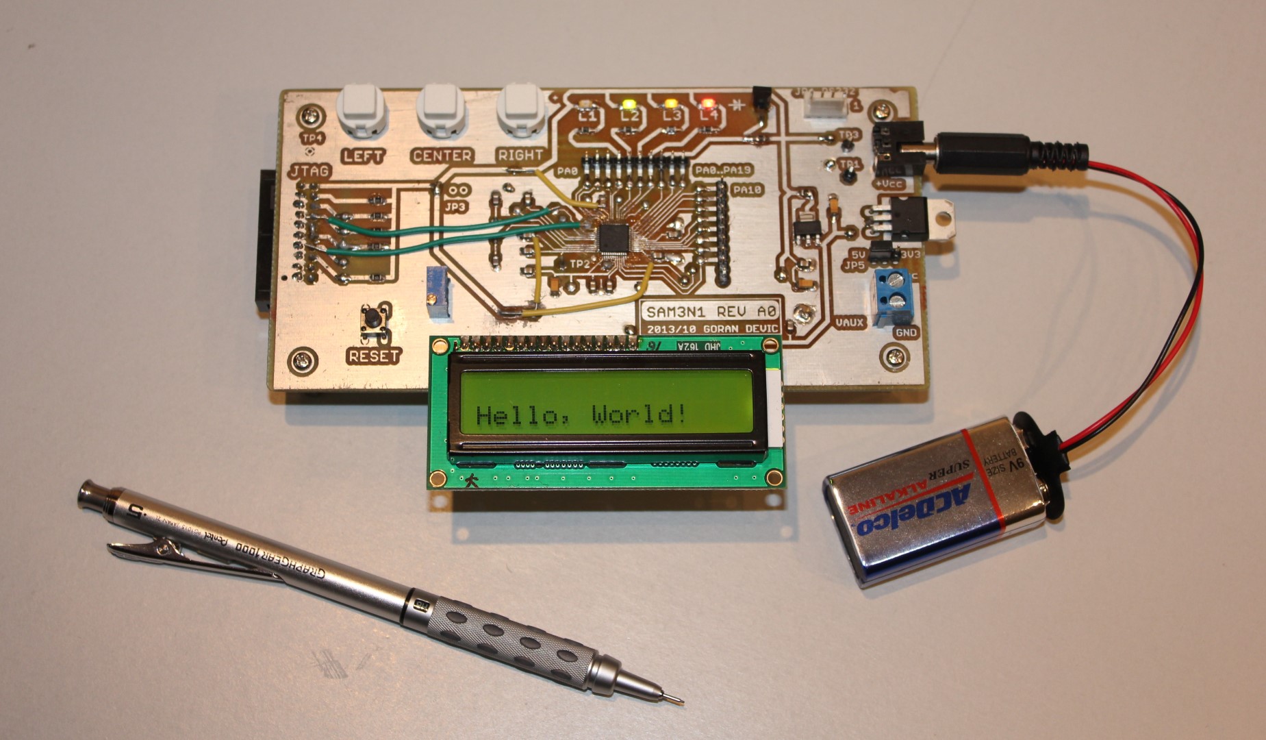
It is useful to have an onboard power switch. I did not add one to this board and I am missing it; plugging and unplugging the power connector causes a momentary bounce where the LCD flickers. I don’t know if that’s harmful or not, but it does not look good when it’s flashing/blinking for a moment.
There you go.
I will try to improve articles if I find better ways of doing it. Thanks for reading!