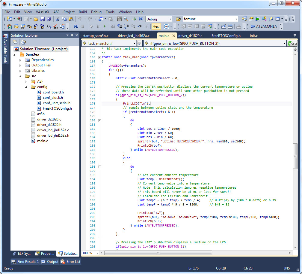
The quality of the tools that we use to write software for projects like this is very important when selecting which MCU we may want to use. Atmel has a very robust IDE based on Microsoft’s Visual Studio (which is arguably the best development environment out there). Coupled with a JTAG interface, writing and debugging firmware with the Atmel toolset becomes a pleasure.
Their ASF (“Atmel Software Framework”) is a good collection of ready-to-use projects and components. Investing time to learn that environment is the best way to become very efficient when using it.
The gist is: before you decide which MCU to use, definitely check out its software support!
While my verification software was chaotic and was using random example code from ASF just to test each component, my final (should I call, production?) software is based on a FreeRTOS. Starting with a FreeRTOS example from the ASF library for the Atmel SAM3N-EK engineering board, I started making modifications and writing drivers for each part on my board. The first thing to change was the basic 16MHz external clock enable. Once that was corrected, I could get FreeRTOS tasks created and run its scheduler.
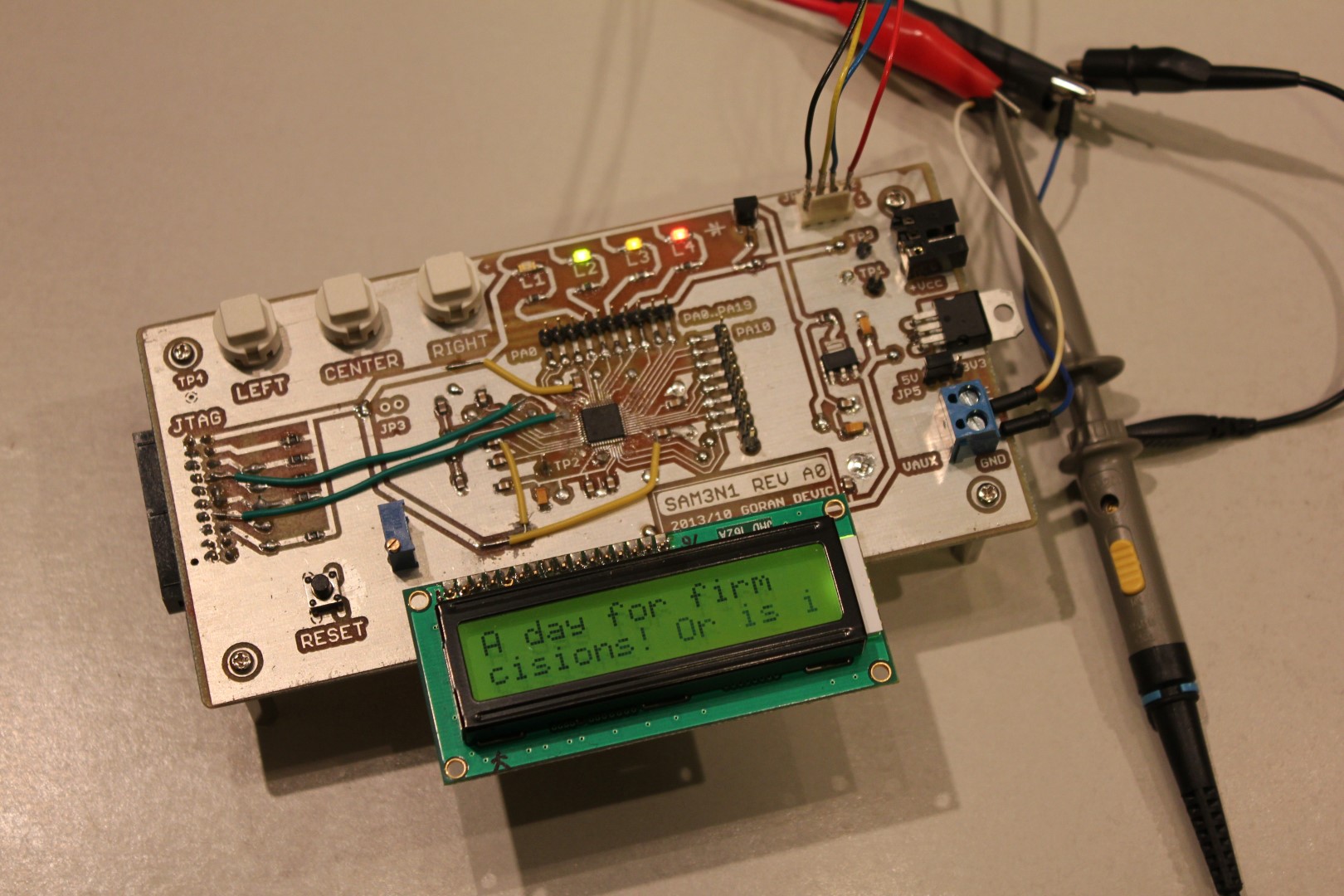
Then I wrote individual drivers for each component (LCD, LED, temperature sensor, serial port, etc.). Controlling LED and pushbuttons was trivial. Getting LCD and temperature sensors working and communicating was more involved.
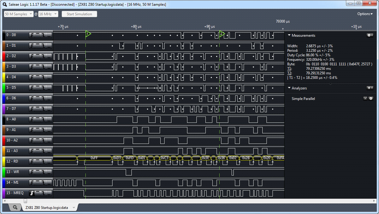
For the temperature sensor, a DS18B20 chip, I used the scope to check the signal quality on the 1-Wire bus. I could toggle its GPIO in software and the chip started responding. Then I connected a logic analyzer and compared the decode of what’s actually happening on that 1-Wire bus to what my code was doing. The timings were critical; 1-Wire depended on it. Eventually, my routines to talk to that chip were solid.
All those things now done, the main task was about to be strung together. I implemented the LEFT button to randomly select a “fortune” quote and display it on the LCD. I have compiled and added a number of “fortune” quotes.
Pressing the CENTER button would toggle showing the temperature and the uptime. I could get the uptime in seconds from the scheduler. This mode keeps refreshing the information; you could hold your finger on the temperature probe and see the number rising.
Pressing the RIGHT button would change the blink pattern of the 4 LEDs and also generate a random number from 0 to 100 just so you have it.
Writing and debugging the software was non-eventful by using Atmel Studio and JTAG.
I did hit one problem, though. By selecting the cheapest variation of that Atmel MCU family (SAM3N1A), I was running out of its quite limited 8K RAM. I had to carefully size and balance various FreeRTOS variables such as OS heap and each task stack size. Next time, I would use a stronger chip variation so I don’t have to worry about these things.
Tools: Atmel Studio, JTAG dongle