This is general guidance for the initial testing.
Thoroughly examine the board for physical defects: are all traces complete or there are breaks?
Are all pins soldered and is the quality of the solder joints acceptable? The soldering point may be missing (forgot to solder it), may have a bridge or a short, or it may be a poor joint (cold point). Just redo it.
Is any component missing? (Something blunt but may happen!)
You may need a magnifying glass or a loupe with a strong light.
Check again the orientation of components: LED, diodes, connectors, chips – where is pin 1 located. Check the orientation of tantalum and electrolytic caps. On SMT components, this can sometimes be confusing.
Check that switches and jumpers are set right for the initial powerup.
Before the initial power-up, check the resistance at the voltage input – it can reveal shorts. If the resistance is too low, it will draw lots of currents and that’s an indicator that something is likely not right.
If you have one, use a bench test power supply that has the current limiter. Set it to minimal expected current. For example, for this board, I had set it to 200mA. I did not really know how much the board will draw with an LCD display and the rest turned on. It turned out it needed between 60mA and 120mA.
Without a current-limiting power supply, initial power-up would be riskier. For a long time, I did not have one. Instead, I made one out of a spare PC power supply and I got by.
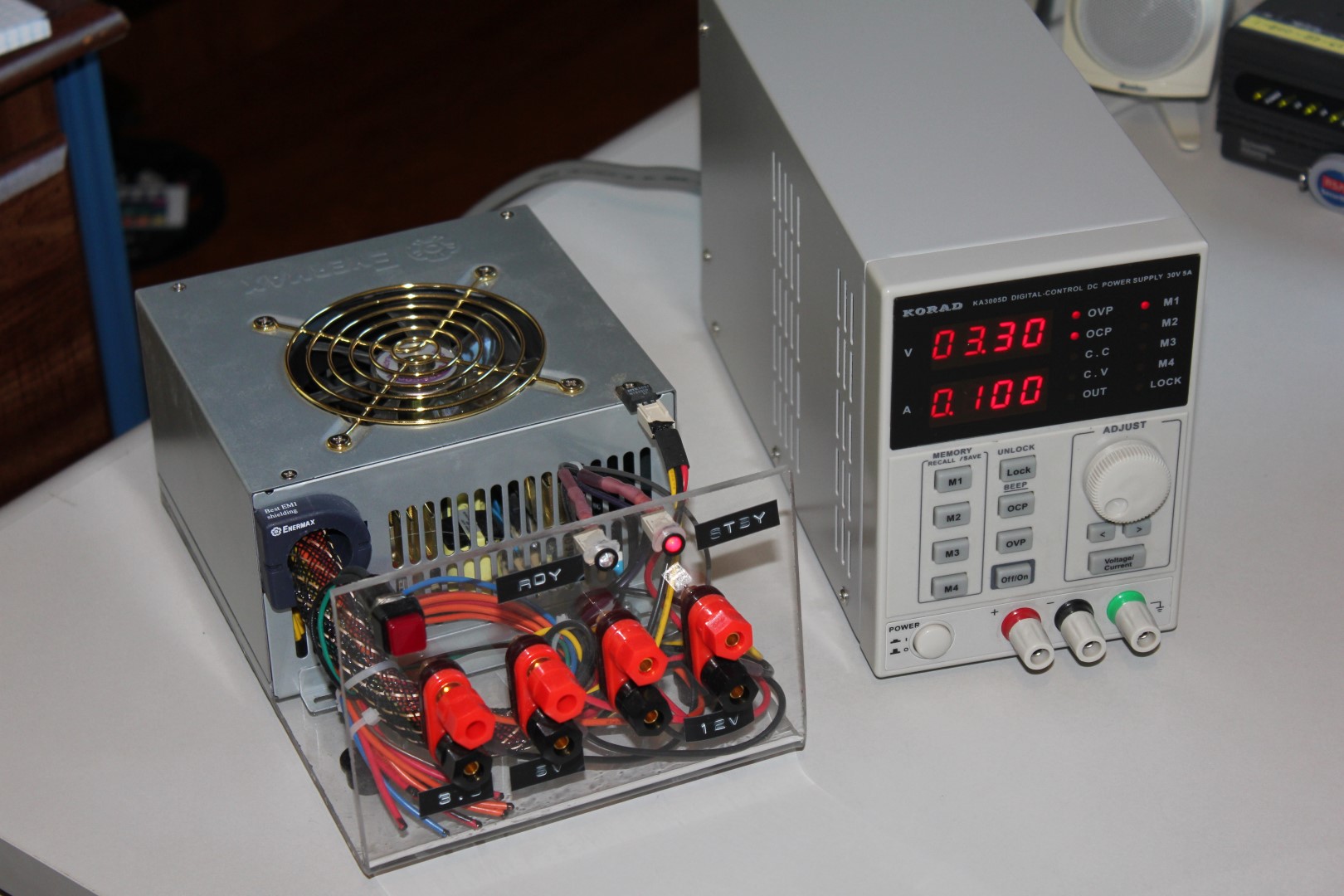
It worked but I was always a bit anxious using it: this beast can easily give you 20 Amps and if you are not careful, you can get hurt or explode your boards.
Eventually, I decided to invest in a good entry-level bench power supply and never regretted it since.
Once the board is powered up, take a moment and see if anything unusual happens. Put a finger on each chip and feel if it gets unusually warm or hot, but be careful! 7805 can get quite hot, very quickly! Smell it. Yes, come close to a board and if you smell anything unusual, quickly disconnect it. It may or may not be too late. Some chips (like 7805, again) are designed to be very robust and can even start smelling for a second and still work later on if you fix the root problem.
If everything feels normal at this point start probing the test pins. (You did put a lot of test pins and pads all over, didn’t you?) Refer to the schematics and probe every power and ground signal making sure they measure what you expect. Probing the actual GPIO or various signal lines may not help since the MCU is not running any program, but do check that all signals that should be pulled up or pulled down actually are. I’ve found several bad solder joints and vias and some of the pull-ups were actually floating.
The following list shows the problems on this board that I’ve had to troubleshoot along with solutions to each. They are listed in the order that I’ve found them.
#1 Soldering the fine pitch of SAM3 MCU’s pins was a challenge. I made lots of solder bridges. At one point I decided to swap it with another one (I had purchased 2) since I thought I killed it. Through all the swapping, re-soldering, and cleaning bridges, I actually got quite good at handling it. The breakthrough occurred when I thought I totally messed it all up and in my mind discarded the whole board. Instantly I became relaxed about it and soldered a perfect row of 0.5mm pitch pins by only dragging a soldering iron over them. Then I fixed bridges by using the edge of soldering wick and things started looking good. Practice makes perfect!
#2 A 16MHz crystal oscillator on the board would not show any signal. Its pins measured flat ground on the scope. This was purely my not knowing of how it works: SAM3 needs to activate external crystal in the software and at that early time it did not have any software. Still, I’ve wasted some time figuring that out: it turns out SAM3 runs on its internal (slow) clock until it is configured to use the external clock. Once properly configured, the crystal will generate a sinusoidal voltage of about 2V on both pins.
#3 A larger problems were SAM3’s VDDIO pins not being connected to 3V3. I traced it to Eagle’s schematics and layout. On the schematics, they were clearly connected and pulled up to 3V3. On the layout, these traces were missing. What was going on here? Well, I made a mistake by incorrectly joining those traces in the schematics. They appeared to be connected, but they were not. Eagle tried to warn me about it when running an electrical rule check, but I marked those warnings away as “approved”. In the future, I will try to address every Eagle warning. This time, I fixed it by jumping 3 wires from each of the VDDIO pins to 3V3.
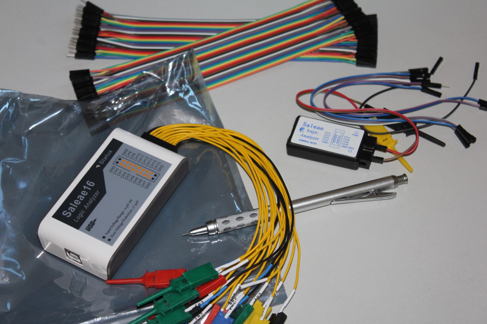
#4 Meanwhile, I kept trying to communicate with SAM3 using the JTAG. Atmel Studio would not recognize the connection. It could read the target voltage, but that was it. I probed each JTAG signal with a scope, but I did not know exactly what to expect. That was a great opportunity to learn about JTAG, signaling, and its protocol. Little by little, signals started making sense. The clock was working. Some voltages were strange (~1.9V). I spent a long time on the JTAG, but that was something that had to be done if I were to see a chip alive. Eventually, I’ve found out that my problem was with PCB vias: few had a poor connection and were introducing a lot of noise and resistance. I soldered jumper wires for several JTAG signals directly to the MCU and that removed the last hurdle to having a board recognized by the Atmel Studio. Once Atmel Studio reported SAM3 chip id, it was an exhilarating moment!
#5 Now it was time to start writing some verification software. Although parts of it may later be reused, that code is different from the final software that will be running on the board. I needed to quickly verify that all components are properly wired and working. I started writing code that toggles GPIOs and one by one each LED lit. One LED remained dark and the problem was (again!) a bad via to it. Re-soldering fixed it.
#6 Backlight of the LCD was also not lit as it was expected to – the backlight should have been directly connected to power so the MCU had nothing to do with it. I was lucky here: I found 2 problems: one where I simply missed soldering the backlight ground. The second was to completely forget to include a resistor on its Vcc. Had the ground been soldered, the backlight would have burned out! The problem started with the schematics. I just forgot to add the part. I fixed it by cutting a trace and soldering a through-hole resistor on the bottom of the board.
#7 Up to this point I have been powering the board through the terminal with 3V3 which was bypassing the rest of the power block. Once connected to 9V, I measured only about 2V at the output of 7805. It turned out I simply forgot to add an input bypass capacitor to it. Again, the problem was back in the schematics. I picked a 2.2uF cap and soldered it underneath the board and 7805 immediately gave a solid 5.0V. I guess that cap is not optional but truly needed by the internal design of 7805. I connected a 9V battery now and the board worked.
#8 Functionally everything appeared all right, so back to the LEDs for a small correction. I’ve seen much stronger SMT LEDs, but these appeared very dim in comparison. The problem was my calculation of current limiting resistors; I was using the wrong values. From the DigiKey website, I was reading the “Current – Test” value which said 10mA while the datasheet specified 30mA continuous or even larger one with PWM (120mA, 10% duty). I swapped the resistors with these:
GREEN Vf=2.1V, Imax=30mA => from 470R to 47R
YELLOW Vf=2.1V, Imax=20mA => from 470R to 68R
RED Vf=2.0V, Imax=30mA => from 470R to 47R
After they were swapped, the LEDs became reasonably bright (the board power usage also jumped from 50mA to more than 100mA with all LEDs on) I did not use PWM for LEDs.
#9 The LCD needed to be initialized in software before it would show anything. I was also not quite sure if this particular controller would even be responding to 3V3 signals (that was a 5V LCD, but its datasheet said it would respond to 3V3). I was using 4-bit programming as well, and in one discussion forum, I’ve found a person saying that 3V3 worked only with an 8-bit data interface. It was a bit discouraging since those were major issues: you can’t easily change voltages or add level translators after the fact. 4-bits interface was using D4-D7 lines and I left D0-D3 floating. Could that also be a problem?
The software also needed to talk to it just right, with all the delays and required intricacies. Eventually, I’ve found in another forum a person saying he got 3V3 and 4-bit interface working proving that can be done. I’ve also found – under a loupe – a very small, hair-thin break in the “enable” wire. Soldering that one, LCD started showing some signs of life.
From then on, it was simply up to the correct programming to get it to display text. This illustrates that there were a number of unknowns with the LCD controller which makes bringing up the interface that much more challenging and interesting.
Each problem was solved, the board functionally looked all right! It was time to concentrate on the final software.
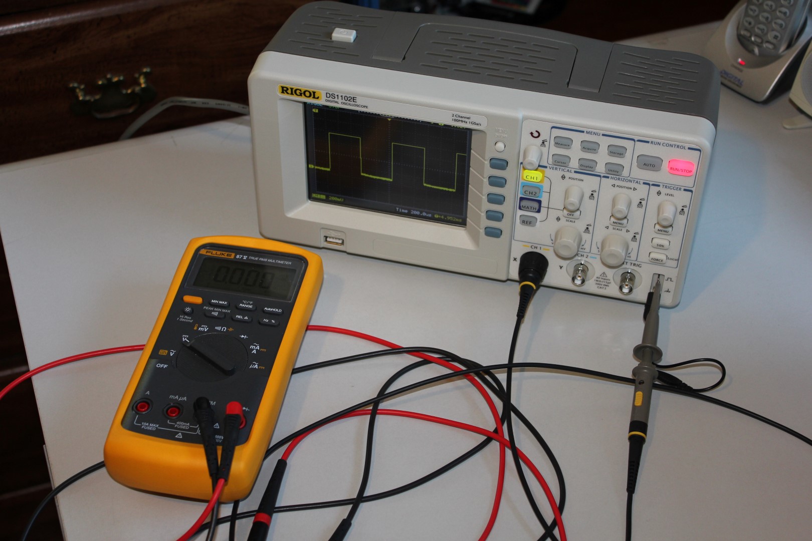
Tools: This step is where you need to pull out everything that you have: current-limiting lab bench power supply, oscilloscope, multimeter; Atmel Studio, JTAG dongle; lots of patience.