


For as long as I remember, I had played with LEGOs. Those simple blocks would transform into complex objects whose final shapes only existed in the supple thoughts of creative imagination. The kind of LEGO blocks we had while growing up were simple: 2×4, 2×2, 1×8. Anything unusual was rare and precious.

For my friends and me, playing with LEGOs from an early age made us think about hierarchical constructions, building blocks, and breaking up the work into smaller steps to build something more complex – all done at the mental level first.
Engineering is, in many ways, just like building things from LEGO blocks. Like a metaphorical “standing on the shoulders of giants” is for the science world, we combine, mix, and match existing pieces and frameworks, carefully introducing new variables only one at a time and testing them with great care before proceeding. We may start with some grand ideas. Sometimes, we are not sure if they are even doable, yet we make repeated attempts to reach them, using different building blocks if needed. The joy is in doing.
In this installment of our calculator building project, I will describe the framework I had set up to have several different practical applications built from a single set of Verilog source code. It uses technologies that span both software and hardware development. When I started toying with it, I was not sure I could get it all to work together in the way I wanted, but it worked out well in the end.
The initial Verilog code around which I built this framework does not do much. Still, it does implement some valuable functions: the “LCD” module implements a complete 16×2 LCD panel driver, which displays “Hello World” after initialization. The 3 LEDs are assigned to blink, showing the pushbutton state and the internal reset state. The 50MHz input clock controls the timing. Pressing the button restarts the sequence. This process is swift, but you might still see a quick flicker on the screen. The states of individual signals are visible in simulation, and there are several ways set up to simulate the design. Each verification approach may uncover a unique set of issues.
While the end goal is to make a physical, electronic device (with a keypad and a display), in the process, we need to test and simulate pieces of that design at several levels and in stages. We will use ModelSim and Verilator software to simulate it; we will debug it and run a prototype using Qt in desktop and web browser environments. Most importantly, the same design will synthesize and flash into a physical test board (with the attached peripherals like LCD and push buttons). The selected Altera EP2C5 prototype board will be a stepping stone to our created and manufactured final board.
Why FPGA?
While we could have used 74-series 5V TTL chips to build this project as it would be considered more of a “retro” style, I wanted to use an off-the-shelf FPGA device instead since it lets me design more complexity at the gate level. (I also did not want to end up with a wired mess of breadboard interconnects.)
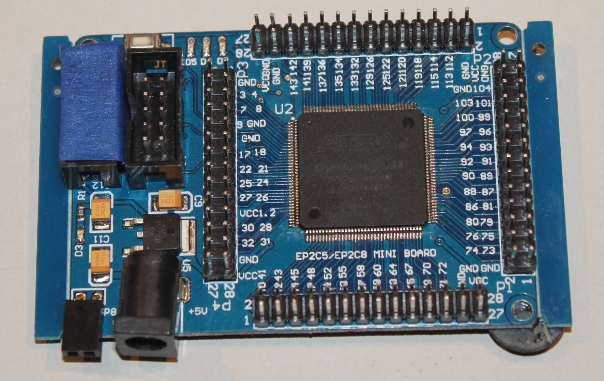
I opted for the Altera EP2C5 due to its relatively low cost (around $5 on eBay), ease of soldering at home (being packaged in a somewhat manageable TQFP with 144 pins), and I also already had an inexpensive test board for prototyping.
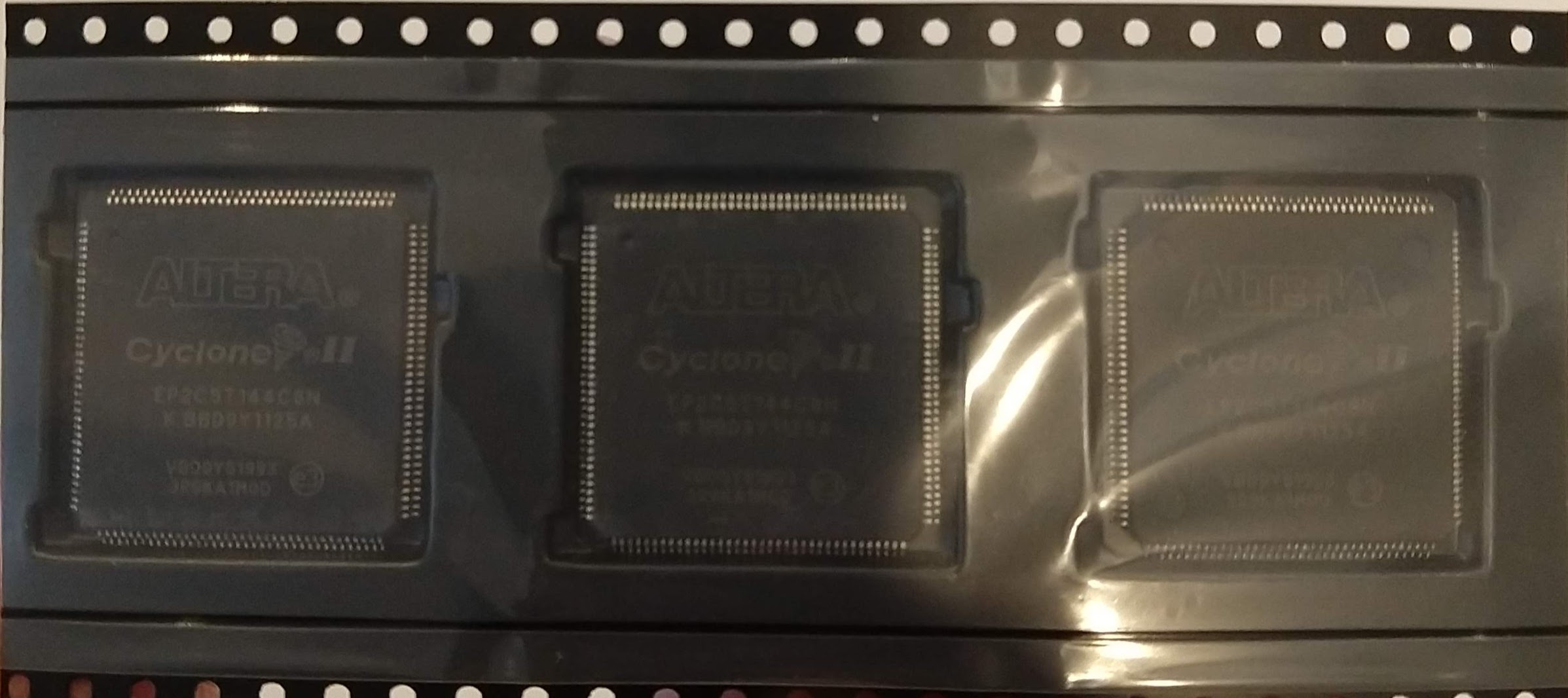
Altera (acquired by Intel in 2015 for $16.7 billion in cash) designs and manufactures programmable logic devices (PLD, FPGA, etc.) and licenses a synthesis tool called Quartus that supports those devices.
If you will, the retro part is Quartus software: when you look at its GUI, it does take you back to the 80s! However, once you get familiar with it and its quirks, the software is not bad, and it does a lot.
To support this FPGA chip generation, you will need an older Quartus version, 13.0.1 (Service Pack 1). The “web” or “lite” editions of Quartus are free. It supports a smaller subset of mostly older FPGA Cyclone and CPLD MAX devices.
Verilator
Verilator is a free and open-source compiler for Verilog (and System Verilog variations) that generates modern C++ code, which can be compiled and executed as an application. It creates a cycle-accurate behavioral software model.
You need to write a C++ wrapper with a main() function, which essentially drives the top module’s clock, reset, and other input pins, and then you can read the state of the model’s wires and nets while running the simulation.
The primary loop in Verilator that runs the simulation:
|
1 2 3 4 5 6 7 8 9 10 11 12 13 14 15 16 17 18 19 20 21 22 23 |
// Simulate until $finish while (!contextp->gotFinish()) { contextp->timeInc(1); // 1 timeprecision period passes... // Toggle a fast (time/2 period) clock top->CLOCK_50 = !top->CLOCK_50; // Toggle control signals on an edge that doesn't correspond // to where the controls are sampled; in this example we do // this only on a negedge of CLOCK_50, because we know // reset is not sampled there. if (!top->CLOCK_50) { if (contextp->time() > 1 && contextp->time() < 10) { top->BUTTON = !1; // Assert reset } else { top->BUTTON = !0; // Deassert reset } } // Evaluate model top->eval(); } |
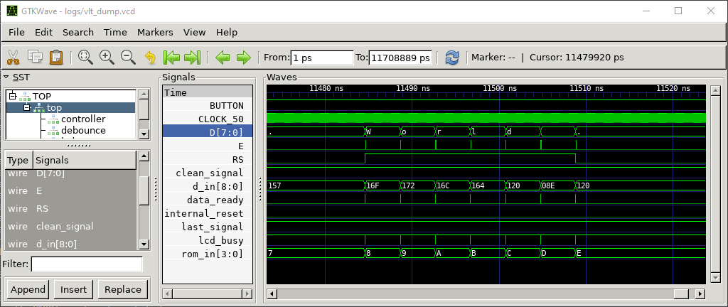
Such a “verilated” code also supports coverage analysis and signal tracing. These traces are written to an external file and can be viewed by the GtkWave utility. Be aware that the trace files can quickly get very large!
If you develop hardware in Verilog (or System Verilog), Verilator can also be used as a good linter (a static code analyzer). It will find errors in your code much faster than any other compilation or synthesis tool. Use it with these options (with your Verilog sources listed at the end):
|
1 |
verilator -lint-only -Wall counter.v |
Qt
Qt is a software framework for creating cross-platform applications using C++. It does it by abstracting everything platform-related with its own set of well-designed classes. So, while you still use C++, standard libraries, etc., you use Qt’s classes to access resources like network, keyboard, and so on.
Qt has more than 2000 classes. Kidding you not: All Classes of Qt 5.15
I have been using Qt professionally and personally for almost two decades, and I’ve used (and am familiar with) only a fraction of the available classes. However, the documentation is abundant and of good quality; plenty of excellent examples and related discussions make it easy to pick up.
Qt is developed and maintained by “The Qt Company” (originally “Trolltech”) based in Finland. Their business model includes commercial licensing at various levels and provides a free, open-source license for non-commercial use.
The beauty of Qt is that once you create an application, you can recompile it to run unmodified on Linux, Windows, Mac, and Android.
QtCreator is an IDE that ships with Qt. Alternatively, if you want, you can compile a Qt app from the command line or import the project into Visual Studio (using a Qt plugin for Visual Studio) if you prefer that IDE. I frequently do that since the debugging capabilities of Visual Studio are unmatched.
We will wrap our “verilated” C++ sources to create a GUI application.
Another benefit of using Qt is that (starting with version 5.15) it supports compiling applications for WebAssembly.
WebAssembly
WebAssembly (or “Wasm”) is a relatively new technology. It is not JavaScript, although it runs in every modern JS virtual machine (in a browser). Wasm was developed with the intent to JIT (Just-In-Time) compile to any modern CPU and provide native performance. It is “client-side,” meaning your browser loads the Wasm object code and compiles it locally before running it. You will notice a rapid spike in CPU usage after loading a web page containing Wasm code and before the code runs.
Currently, the primary tool to compile your C++ source to Wasm is called “Emscripten.” Some other languages are also supported; for example, Microsoft’s Blazor compiles C# into Wasm.
Wasm has two standard formats: a compact binary object file and the corresponding, human-readable listing. The binary object still needs a JavaScript wrapper to load it and to provide the sandboxed environment in which it can execute. Hence, the final code bundle includes both the JavaScript wrapper and an HTML page it is embedded in. The Wasm API requires a level of support provided by the sandbox to interface with the “outer world” safely. As a developer, you would need to write that glue logic.
Fortunately, Qt takes care of that wrapper for you. You compile your C++ code just as you would a typical Qt application, and it should work. Not all Qt classes have been ported to Wasm yet, but the list is growing. Also, some functions are modified since the Wasm runs in a protected sandbox. For example, standard file dialogs to load and save files are implemented as browser file upload and download operations. As Qt is constantly evolving, I am sure they will iron out those kinks as much as possible, given the inherent limitations of the environment.
Since the WebAssembly code is running within a protected browser VM and it cannot access the host file system, and because our async_rom module needs to read the initial ROM content from a file (“lcd_cmd.txt”), we need to resort to a trick. To provide that file inside a browser’s sandboxed VM, we store it as a resource in the Qt app, and then we copy that resource back to the file on the host when the app starts:
|
1 2 3 4 5 6 7 8 9 10 11 12 13 14 15 16 17 18 19 20 21 22 23 |
int main(int argc, char *argv[]) { QApplication a(argc, argv); #ifdef QT_DEBUG // In debug mode, use the resources from their source location since the qrc file // is not being refreshed (unless fully rebuilding). This saves time, but will // not work in WebAssembly. We don't debug in that environment, anyways. QFile::remove("lcd_cmd.txt"); // copy will not force... QFile::copy("../verilog/lcd_cmd.txt", "lcd_cmd.txt"); #else // Copy resource file into the file system on the target platform // so it can be read by the async_rom module (using the $readmemb function) QFile::copy(":/lcd_cmd", "lcd_cmd.txt"); #endif // QT_DEBUG ClassSim sim(argc, argv); MainWindow w(&sim); w.show(); return a.exec(); } |
Quartus
The “quartus” folder contains project files for Altera (Intel) Quartus software. To support Cyclone II devices, you need to download Quartus version 13.0. SP1. The project was set up to synthesize on that FPGA device and to download/flash our test board.
Cyclone II EP2C5 Mini Dev Board – Land Boards Wiki (land-boards.com)
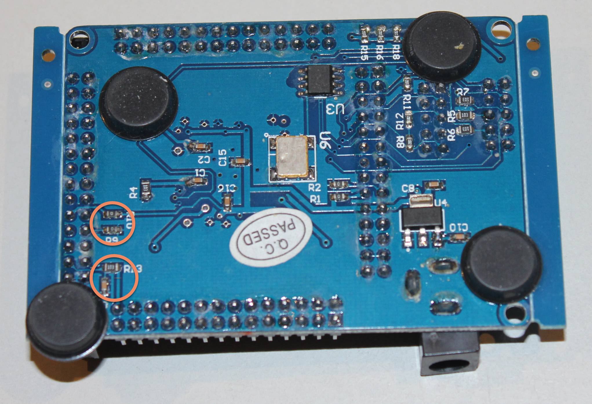
I performed some minor modifications to that board: I removed a couple of resistors and capacitors to free up a row of GPIOs. Those SMD components were not used for the core FPGA operation. They were added to support external reset and a different device SKU using the same board. On that board’s website, the components are mentioned as “Only needed for EPC28”.
ModelSim
ModelSim is an HDL simulator made by Mentor Graphics. Founded in 1981 and based in Oregon, it was acquired by Siemens in 2017. The company develops and licenses a range of EDA (electronic design automation) tools, of which ModelSim and QuestaSim are just two. While QuestaSim is their newer and more expensive flagship product, ModelSim is an older and now mostly free for students and hobbyists.
You can download the free versions of ModelSim alongside the Quartus tool from the Intel website. Both are sufficient for smaller projects using older FPGA chips.
Our project’s “modelsim” folder contains a ready-to-run configuration. After ensuring the ModelSim executable is in your path, run “modelsim.bat” from a command prompt, and the script will do the rest: create a project, include relevant Verilog files, compile, and run the simulation. At the end of the simulation, the code will encounter a “$finish” statement (located in the “controller.sv” file) and stop. If you do not want the source file to open at that point, change ModelSim setting by Tool->Preference->By Name->OpenOnFinish = 0.
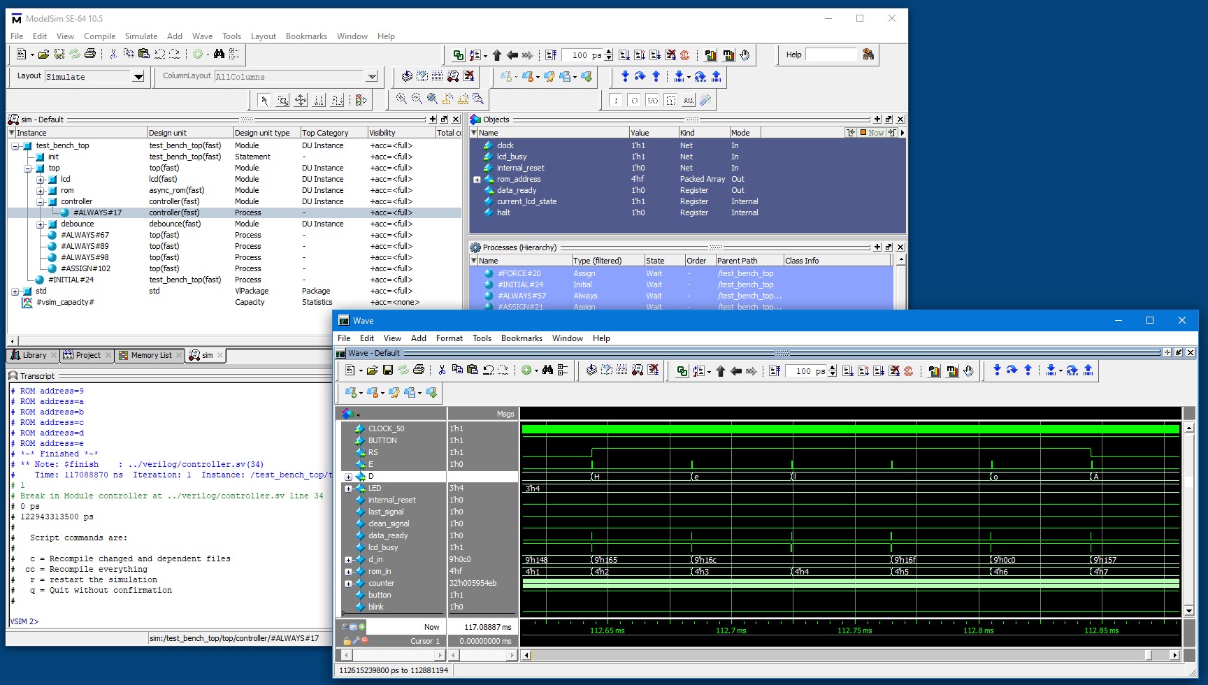
The results
This development was done on a Windows 10 machine (most recently I have switched to a Windows 11 OS). Verilator and GtkWave were run within a WSL2 (Windows Subsystem for Linux). The MobaXTerm application provided the X-11 server on Windows. If you try to replicate this setup and encounter problems opening an X-window from within WSL, be sure to set Linux’ DISPLAY environment variable in this way:
|
1 |
export DISPLAY=$(grep -m 1 nameserver /etc/resolv.conf | awk '{print $2}'):0.0 |
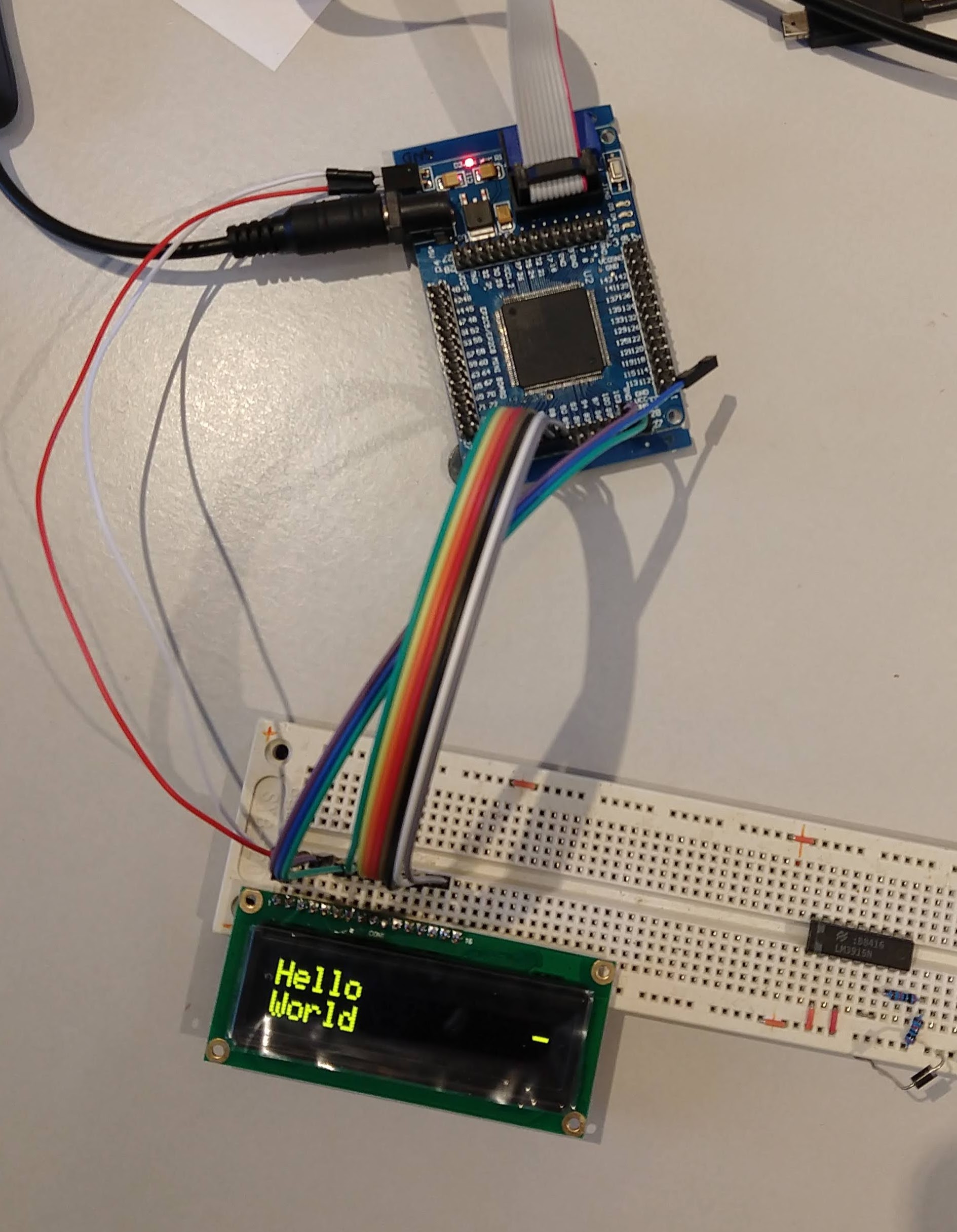
Here is “Hello, World” displayed running on an Altera FPGA board:
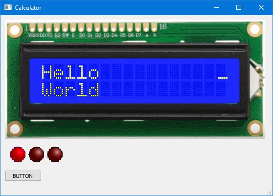
The same Verilog code, verilated and compiled as a Windows application:
Compiled to Qt’s WebAssembly target, the same application runs in a browser:
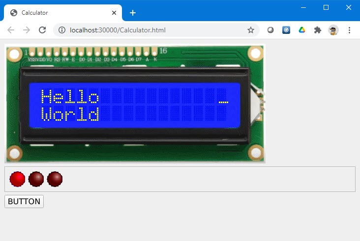
I have copied the code here where you can run it from your browser:
This framework’s beauty is that the basic Verilog source code runs un-modified in a variety of build and test environments, producing identical results. Another good thing about this project is that all the tools for it are free.
These technologies are like LEGO pieces; we picked them from a pile of available technologies, connected them with some glue logic, and, after much experimentation, we built something quite versatile.
I am leaving it in that basic form that can serve as an initial template for a similar project.
Next article:
Additional Links:
- The LCD Verilog driver is based on FPGA to 2-Line Text LCD Interfacing (hobbizine.com); (I modified it for System Verilog.)
- 16×2 LCD software emulator, HD44780U Character LCD Emulator (github.com)
This project is certainly impressive !!
One question I had in mind is, are all the algorithms for the complex calculations (such as trig functions or log) implemented exclusively in the FPGA ?
Not directly at the HDL level. They are implemented in microcode for a custom CPU, which itself is implemented in “hardware.”