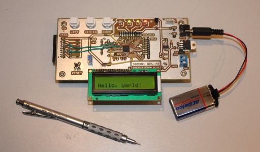
PCB Making: 1. Introduction

"Hello, World!"
“Hello, World!”

This set of short articles will show you the making of a PCB, from the initial requirement stage, through the design and manufacture, and to final software programming.

If you are new to PCB making, I am hoping this text should paint some basic picture of what is involved in a home board design and manufacture. If you are already an experienced hobbyist, I hope you will find some parts informative or interesting enough to try them yourself on your next project. If you see anything wrong or have a better way of doing it, please post it in a comment. I will appreciate learning from you and sharing the experience!

Continue reading

PCB Making: 2. Get Started

This is a step of looking for an idea or for the purpose of what a board should be doing. You will likely know what you need and then build a suitable board. I needed to build something useful so I can look forward to it once it was done: I wanted to be able to interact with it but also use parts that I already have at home.

In my parts bin, I found a fairly standard LCD display that I got with an Arduino board. It can display 16 characters in 2 rows. This should be a good display device to use.

Continue reading

PCB Making: 3. Schematics

The software I use to create board schematics and layouts is Eagle CAD.

Software-wise, I also use git version control: I frequently version and commit all changes to project files and then upload them to a cloud server. I like GitHub and BitBucket servers which are free. My suggestion is to always version your work and to always backs it up.

There are a number of great tutorials on the web about using Eagle and git, so I will not go into it here.

Continue reading

PCB Making: 4. Layout

When you switch to Eagle’s layout editor, all the components are going to be grouped together in a corner. Yellow lines (“air wires”) will connect pins. A good way to start untangling that mess is to separate and group components that belong to each design block. For example, the power block contains 7805 and a couple of caps and connectors or terminals. Then you can move them around as groups and play with the placement to get a feel of where they would fit on the final board.

Continue reading

PCB Making: 5. The Mask

Before placing (expensive) transparency into a laser printer, I do several test prints using regular paper.

When you print a transparency mask always invert the TOP layer so that the ink die is close to a board when sandwiched and the thicknesses of a transparency foil are not in the way => print with MIRROR option checked.

Double-sided
TOP: select (1) Top, (17) Pads, (18) Vias, (20) Dimension and MIRROR option
BOTTOM: select (2) Bottom, (17) Pads, (18) Vias, (20) Dimension. Do not print with MIRROR.

Single-sided
BOTTOM: select (2) Bottom, (17) Pads, (18) Vias, (20) Dimension. Do not print with MIRROR.

Don’t forget to do the ground pour before the printing! The ground pour will flood selected signals (usually ground) over empty space on the board.

Continue reading

PCB Making: 6. Cut a Board

I am using pre-sensitized FR-4 boards. You can also buy something called, “paper phenolic” board; I don’t have experience with those. I used to buy boards from a local Fry’s but lately I just pre-order them from any eBay listing (China) where I can get several for the price of one.

Continue reading

PCB Making: 7. Expose and Develop

You can buy or build a special enclosure with a timer and light to expose your boards. Although building it is probably an interesting project unto itself, I’ve found that a cheap desk lamp that I’ve found at a Home Depot discount rack one day, coupled with a simple daylight CFL (“Compact Fluorescent Lamp”) bulb, does the job perfectly. For consistency, I use that lamp (and the bulb) only for this task. Therefore, the bulb has only a few hours of usage and it’s still at its full brightness capacity.

Continue reading

PCB Making: 8. Etching

There are several kinds of etchants; I am using Ammonium persulfate solution from MG chemicals. It comes as loose powder or crystals. The content releases gasses over time, so you should punch a small hole on the lid of its plastic bottle. These are dangerous and corrosive chemicals, so use a lot of common sense when working with them. There are several variables in the process that you can try to control for the most efficient etching. The goal is to have the shortest etching time and minimal use of etchant chemicals. There is a sweet point in that compromise and you can reach it by experimentation.

Continue reading